Adding a 3D Clipping to an Exact View | ||||||
|
| |||||
-
From the View Layout section of the action bar, click Add 3D Clipping
 .
.
-
In the Clipping dialog box, under
Characteristics, click any one of the following
options:
-
Back clipping
 : To select 3D elements positioned ahead of the plane. The arrow indicates the front face of the
clipping plane.
 -
Slice clipping
 : To select 3D elements between the back and the front clipping
planes.
 -
Box clipping
 : To select 3D elements inside the clipping box. By default, this clipping mode is
selected.
 -
Volume clipping
 : To select a space allocation volume.
Note:The elements intersecting the clipping planes are cut.
Back Clipping Slice Clipping Box Clipping 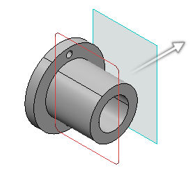
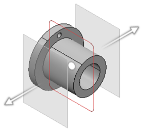
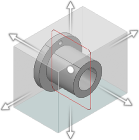
-
-
Under Parameters, perform either of the following
operations:
- Enter the values in the boxes.
- In the 3D viewer, drag the arrows to the required position.
You can select a point, a line, a plane, or an axis, as a reference element.
Tip: Global manipulation for slice and box clipping: Click the dot manipulator between the arrows to move the clipping tool. Click in the empty space to exit this mode. In case of box clipping, you can also rotate the clipping tool. - In the 3D viewer, click the arrow and select a reference element.
After clicking the arrow, the following options are available for translation of planes during reference selection:
- Snag clipping tool to plane
 : Moves the clipping tool with respect to the selected
reference element.
 - Translate plane to geometry
 : Moves the plane according to the selected reference
element.
 - Translate plane to bounding box
 : Lets you select the planes using the bounding box of the
selected element. The bounding box defines two alternative
reference faces. The selected face is highlighted with cyan
color.
 - Translate plane along main axis
 : Lets you translate the plane along the main axis. By
default, this option is selected.
- Snag clipping tool to plane
-
Under Display, click the following options to change the visualization accordingly:
- Clipping tool:
- Display background and clipping tool
 : Shows the 3D object and the clipping tool.
 - Display clipped background and clipping tool
 : Shows the clipped 3D object and the clipping tool.
 - Display clipping tool
 : Shows only the clipping tool.
- Display background and clipping tool
- Transparency: Modifies the transparency of the clipping tool. By default, the value is 200.
- Turn viewpoint: Turns the viewpoint of the 3D object to Iso, Front, Rear, Left, Right, Top, or Bottom.
Back Clipping Slice Clipping Box Clipping 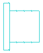

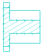
- Clipping tool: