Compute Corners and Thicknesses | |||
| |||
-
Click Compute corners.
The corner operation is applied manually on the sharp vertices in the Section join node.

The default corner radius defined in the dialog box is used for all created corners. However, you can independently modify each corner radius by double-clicking the radius value in the work area.
Note:- When a corner generated using Compute corners is absorbed by another corner operation, the 3D display remains, allowing you to modify it manually.
- A corner value of 0 preserves the sharp edge as it is.
- You can click Remove corners to remove the corners which are generated by Compute corners.
- If you change the corner radius value, corners must be removed first for recomputing with the modified value.
- If the corner on vertex is not available, corner on elements will be created.
Specifications for corner on element on any particular sharp vertex to be
cornerized will be as follows:
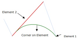
- If none of its adjacent sharp vertices are already cornerized: Distance
between the vertex to be cornerized and the adjacent sharp vertices on both
sides are computed. The vertex with minimum distance from vertex to be
cornerized is taken as Element 1 and the edge on the other side of vertex to be
cornerized is taken as Element 2.
- If one of the adjacent sharp vertices is already cornerized: The adjacent
sharp vertex is taken as Element 1 and the adjacent Edge+Corner is taken as
Element 2.

- If no solution with these inputs, C0 solution will be computed. The adjacent non sharp vertex is taken as Element 1 and the edge between current vertex and adjacent sharp vertex is taken as element 2.
- If both the adjacent sharp vertices are already cornerized: Distance between the vertex to be cornerized and the end vertices of corners on adjacent sides are computed. The Edge+Corner on the side of farther vertex is taken as Element 2. The Vertex between the adjacent Edge and corner, on the nearer side is taken as Element 1.
- If none of its adjacent sharp vertices are already cornerized: Distance
between the vertex to be cornerized and the adjacent sharp vertices on both
sides are computed. The vertex with minimum distance from vertex to be
cornerized is taken as Element 1 and the edge on the other side of vertex to be
cornerized is taken as Element 2.
-
Select the Automatically compute undefined corners check box to apply a new corner operation on undetermined vertices which may remain after the compute corners operation.
Undetermined vertices are sharp vertices introduced after being created using Compute corners.
Note: This check box does not affect sharp edges which result from setting their radius to zero during the corner computation.When this option is used prior to creating the corners with Compute corners, it systematically applies the default corner radius on all sharp vertices.
-
Select the Thickness check box and enter a value to compute the thickness.

This option can be applied on the result of a corner operation or on the elements of the Section join group if no corner operation has been defined. It is composed of a parallel curve followed by a closing lines operation.
The closing lines operation is performed when the characteristics of the body representing a 2D-view thickness feature match with the characteristics of the body representing a section join feature. For example, the closing line operation is possible when the number of domains in input body and output body is the same.
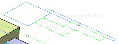
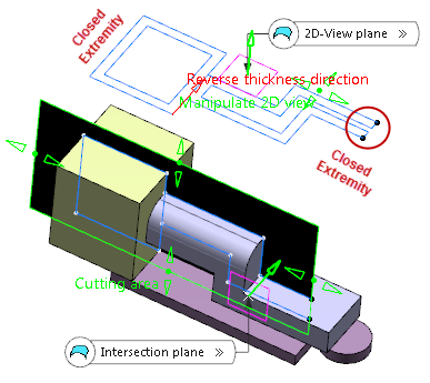
Tip: You can click Reverse thickness orientation in the dialog box or the arrow in the work area to reverse the orientation of the parallel curve: 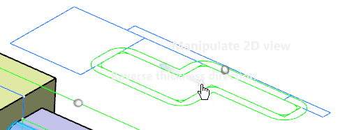
Note: The thickness and corner operations use the visualization plane (or planar surface) as a support. If a bounded planar surface is used as visualization plane, all elements on which the corner and thickness operations are performed must lie within the visualization planar surface. Otherwise, the operation fails and a warning message appears. - Optional:
Select the Open/Close Extremities check box to open the thickness at either extremity.
The Open/Close Extremities option is only available if Thickness check box is selected.
Depending on the position of the cutting area with respect to the cutting element, you may get the following results:
- The cutting area lies inside the limits of the cutting element:
Open/Close Extremities check box is selected Open/Close Extremities check box is cleared 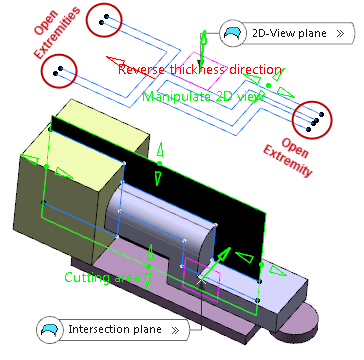

Thickness at both the extremities is open. Thickness at both the extremities is closed. - Cutting area lies outside the limits of the cutting element:
Open/Close Extremities check box is selected Open/Close Extremities check box is cleared 
Thickness at the right extremity is open, while at the left it is closed, due to cutting area exceeding the cutting element. Thickness at both the extremities is closed.
- The cutting area lies inside the limits of the cutting element:
- Optional:
Select the Vertices list
tab.
It displays all vertices at the sharp corners of the 2D-view section.
The vertices are sorted as follows:
- If the curve contains only convex or concave corners, the vertices are sorted in descending order of their radii.
- If the curve contains convex and concave corners or sections with consecutive convex or concave corners, all vertices of the convex corners are listed first followed by the vertices of all concave corners unless Thickness option is used.
If Thickness is defined and the direction reversed using Reverse thickness direction, the convex - concave order is reversed, i. e. in this case the vertices of concave corners are computed first.
By default, all consecutive vertices of the same type are listed in descending order of their radii. However, this is no longer valid if the order is changed manually using the Move up or Move down button.
Note: The list is dynamically updated when changing a radius, provided the vertices order has not been modified using a manipulator in thework area or the Move Up and Move Down buttons in the dialog box.Curve with two sections containing convex and concave corners 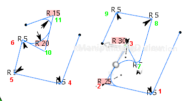

The vertex numbers of convex corners are displayed in red and vertex numbers of concave corners in green.
Radii causing modifications of the vertex position in the list are highlighted.
