-
From the
Automotive
section of the
action bar, click Insert 2D-View Section
 . .
-
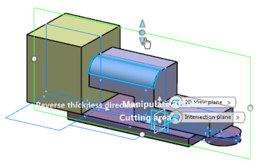
In the 2D-View plane box, select the visualization plane or planar surface.
-
In the Intersection plane box, select the cutting plane or planar surface.
Note:
Both planes may be identical, parallel, or unrelated. You can create a
2D-view section with only these two inputs, however, the created 2D view section is very
similar to a geometrical set or an ordered geometrical set.
-
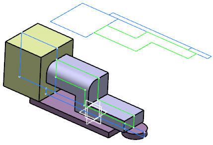
Select whether you want to show only the 2D view (2D-View only) or the 2D view and the 3D intersections (2D-View + intersection) in both view and intersection planes.
-
In the Content of list, select where you want to put the
selected geometrical elements: either to a new group if none exists already (as in our
scenario) or an existing group (Group.x).
-
In the Group Color list, select the color of wireframe objects for the current group.
Note:
The geometries selected in the Cut elements in
group area may be arranged in different groups. Every group has its
defined color to distinguish the generated wireframe objects created by intersecting
geometries of every group with the intersection plane. Intersection and visualization
planes must be common to all groups.
-
In the Cut elements in group area, select the geometrical
elements of your choice (curves, surfaces, volumes, or solids) to be inserted in the
current group.
Note:
You can select the element and click Remove to delete it from
the list.
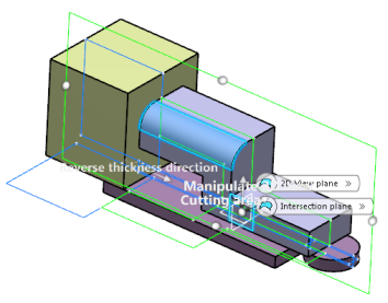
On the cutting plane, a rectangle with handles appears.

-
Modify the size of this rectangle using the handles.
The rectangular area is frozen i. e. automatic dimensioning
does not work anymore when adding or removing elements from the intersected geometries.

-
Right-click any of the handles of the cutting plane and select Reset to default position.
The delimiting rectangle is reset to its initial position and the intersecting element is the bounded cutting surface originally selected. Note:
This context menu is only available with the modified rectangle.
- Optional:
From the Cutting Area Dimensioning
tab, select a point in the Reference Point box and define width and height to specify the dimensions of the cutting area.
Note:
If the reference point lies outside the cutting plane, it is projected onto the cutting plane.
-
In the Cut elements in group list, select one or several elements and New Group among the possible destinations from the list. Click Move to.
The selected elements are moved to a new group.
-
Select another color for this new group in the Group Color list.
-
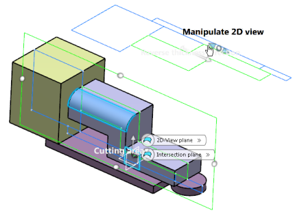
Use the 2D view handles to move the 2D-view section for a better visibility.
-
Click OK.
 The 2D-view is created in the current In Work Object. In the tree, for each group is generated a node under the 2D-view section feature.
- Optional:
Click Filter the Section's components
 to hide all nodes of the tree under the Group node.
|
 .
.

 to hide all nodes of the tree under the Group node.


