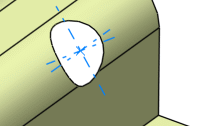
-
From the
Automotive
section of the
action bar, click Hole
 .
.
-
Select one of the following shapes: Round,
Slot (elongated hole),
Rectangular, or Square.
The shape is defined on a plane and projected on the surface along the
defined direction. The nearest projection is used.
- In the Center Point box, select a point.
- In the Support surface box, select a reference surface.
-
In the Orientation box, define the orientation to align
the major axis along the direction.
- In the Punch direction box, specify the direction.
- If the point lies on the support surface, by default, the punch direction is the normal direction at the center point.
- If the point does not lie on the support surface, you must define a punch direction.
- By default, the Axis Computation check box is selected to automatically create an axis and direction lines passing through the center of the hole.
One of the direction lines is created along the input orientation direction. The other direction line is created mutually perpendicular to the axis and the first direction line.
- Select the axis type.
| Option | Description |
|---|
| Finite Axis |
Creates lines of finite length. The length depends on the type of the hole shape:
- Round: The axis length depends on the diameter.
- Slot: The axis length depends on the slot length and width.
- Rectangle: The axis length depends on the rectangle length and width.
- Square: The axis length depends on the side of the square.
|
| Infinite Axis |
Creates axis lines of infinite length. |
Note:
The selection of the Axes visualization limited to the bounding box of the input check box in
> Generative Shape Design, General
tab, has no influence on the visualization of the hole axis.
- To create the axis along the punching direction, select the Axis Normal to Surface check box.
The axis lines are created in the normal direction to the support surface.
-
Click Preview.
-
To specify the shape dimensions, do one of the following:
- Click the value to edit.
- Click the Size
tab.
- Click OK to create the hole.
The element (identified as
Type Hole.xxx) is
added to the
tree.

Note:
If several solutions are possible, the solution with the
minimum distance is chosen. If all distances are equal, a message is displayed,
asking you to modify the point position.