-
From the
Morphing section
of the
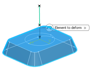
action bar, click Bump
 . .
- In the Element to deform box, select the curve or the surface to be deformed.
- In the Limit curve box, select the limiting curve to
delimit the deformation area.
The limit curve must lie on the element to be deformed.
- In the Deformation center box, select the
point representing the center of the deformation.
The deviation will be maximum at this point, and evolve towards the limit curve, where it should reach 0. 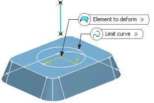
- In the Deformation
direction box, select the curve indicating the deformation direction.
The deformation is propagated along this direction. By default, the deformation direction is normal to the deformed element. 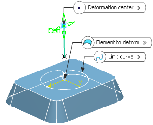
- In the Deformation distance box, set the maximum
distance, along the deformation direction, from the deformed
surface towards the deformation center.
-
Click Preview.
-
Click Add Parameters>> to display
Additional Bump Parameters.
- Continuity: Defines the continuity to be kept
between the deformed area and the surface outside the deformation area
(point, tangent, or curvature continuity).
- Projection direction: Specify a projection
direction if the deformation center does not lie within the selected element
to be deformed.
- Center Curvature: Define a center curvature value
to control the shape of the bump deformation. If the value is:
- Equal to 1 (case A), the shape is the default one (as if no value
was defined)
- Smaller than 1 (case B), the shape is flatter
- Bigger than 1 (case C), the shape is steeper.
Note:
All values are allowed (positive, null, and negative values),
however it is advised to define a value comprised between -1 and
5.
-
Click OK.
|

