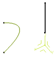
- Create two points using the following coordinates:Point.1: X=0, Y=0, and Z=22 Point.2: X=0, Y=0, and Z=75.

- Define a line between these two points.It is created along the Z axis of the axis-system, using the Creating Lines option.
- From the Tools section of the action bar, click Law
 .The Law Editor dialog box appears in which you name the law to be created, give it a description and a storage location.
 - Click OK.The Law Editor dialog box is updated. The right-hand part allows you to create the parameters to be used in the law. The left-hand part is the law edition box.
- Create one real type parameter t and one length type parameter x, then enter the law below into the edition window: x=40mm+100mm*(t-0.5)**2.
- Click OK to create the law.
- Create a second law using one real type parameter t and one length type parameter y, then entering the following law into the edition window: y=40mm+200mm*(t-0.5)*(0.25-t)*(0.75-t)
- Create a parallel curve,
using the line created in step 2 as the reference Curve to
be offset and the ZX plane of the axis system as the Supporton which the reference curve lies.
- Click Law... and select Law.1 from the tree.
- Click OK.
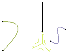
A curve parallel to the selected one is created, taking the law into account, that is, it is defined by the equation entered as a law using the Engineering Rules Capture app.

- Create a second parallel curve, using Line.1 as the reference Curve and the YZ plane as the Support.
- Click Law... and select Law.2.
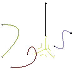
- Click OK to create the parallel curve with a
variable law.

- Use the Combine command to
create a curve resulting from the intersection of the extrusion of the
two parallel curves.

- Use the
Project
command to project the combined curve onto the xy plane.
- Select the combined curve as the element to be projected, the xy
plane as the Support, and the Z axis as the Direction.
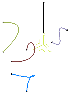
Here is the parameterized curve (in blue) obtained by two formulae:

Important: It is recommended to create closed parameterized curves.