Create a Styling Fillet between Two Surfaces
You can create a styling fillet between two surfaces using the different continuity and fillet types.
-
From the Refine section of
the action bar, click Styling Fillet
 .
.
- Under the Options tab:
-
In the Continuity area, click
 continuity.
- In the Fillet Type area, cancel the selection of Variable \ Partial Fillet
 .
.
-
In the Continuity area, click
-
Select two surfaces.
Input surfaces can be intersecting or non-intersecting.
In case of non-intersecting surfaces, specify the edges of the input surfaces to extrapolate so that they intersect. A message is displayed asking you to give the input edges for extrapolation. The input edges must be the border edge of the input surface and must be G1 continuous. If the edges are not G1 continuous then an error message is displayed. When the given input edges for extrapolation fail to find an intersection between the given set of input surfaces, an error message is displayed.
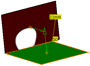
Two vector arrows, the G0 continuity symbol and a radius value appear.
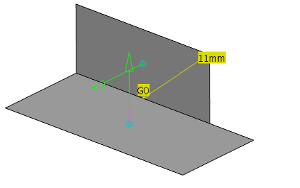
- Click Apply.A G0 fillet appears.
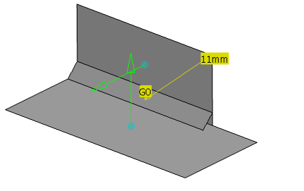
-
In the Continuity area, click
 continuity.
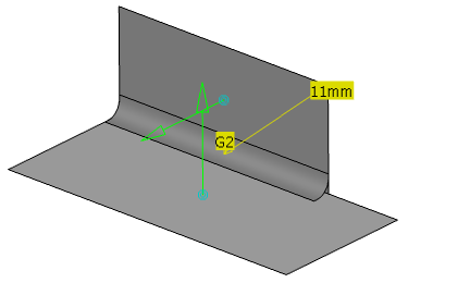
- The G2 continuity symbol appears.
- The fillet color changes to red indicating that it does not represent the current selections in the dialog box.

- Click Apply.
A G2 fillet appears.
Note: Drag the Robot to the geometry of an existing styling fillet to directly modify the fillet radius. In this case, the feature is selected and the handle with the radius parameter is displayed. You need to drag the handle to set the required radius value. - To shrink the fillet, modify the start and end points of the intersection curve:
-
In the Fillet Type area, click
Variable\Partial Fillet
 .
The intersection curve between the input surfaces is displayed and at the fillet extremities, handles with a radius value appear.
 - Drag the handles along the intersection curve towards the center of the fillet.
- Click Apply.
The fillet result is shrinked to the new handle positions.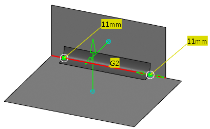
-
In the Fillet Type area, click
Variable\Partial Fillet
- Adjust the fillet radius to vary linearly along the length of the fillet:
- Click one of the radius values and change its value in the Edit dialog box.
- Click Apply.
The radius varies linearly from one end of the fillet to the other. Note: You can snap the handle to define the intermediate radius position of a curve intersection:
- Hold down Shift or click Snap on Edge in the App Options panel.
- Move the handle over a curve to display the position of the intersection between this curve and the guiding curve of the handle.
- Release the left mouse button to snap the handle on the intersection.
If a curve does not intersect the guiding curve of the handle, the snapped point on the guiding curve is at a minimum distance from the selected point on the curve.
- Adjust the fillet radius to vary non-linearly along the length of the fillet:
- Click one or several positions on the intersection curve.An additional handle is created at each position.
Tip: To remove an additional handle drag it to the end of the fillet or select Delete this Point in the context menu. - Define different radii at each inserted position.
- Click Apply.
The radius varies non-linearly from one end of the fillet to the other.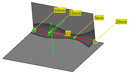 Note:
Note:- When multi-domain intersection is found between Select surface set 1 and Select surface set 2, this option is not available.
- The surfaces involved by the selected elements in Select surface set 1 must be G1 continuous to generate a continuous variable fillet.
- Click one or several positions on the intersection curve.
-
Click
OK.
A styling fillet is created in the tree under the PartBody node.
