Create an Axis System from Coordinates and Geometry
-
From the Wireframe section of the
action bar,
click Axis System
 .
The Axis System Definition dialog box appears. The axis system's parameters Origin, X axis, Y axis, and Z axis are automatically computed, and Default (Computed) appears in the boxes.
.
The Axis System Definition dialog box appears. The axis system's parameters Origin, X axis, Y axis, and Z axis are automatically computed, and Default (Computed) appears in the boxes. -
Select the Axis system type.
-
Standard: Defines the axis system by a point of origin and three orthogonal directions.
- If an axis system is defined as current, the new axis system is a copy of this current axis system.
- If an axis system is selected, the new axis system is a copy of this preselected axis system.
- If no axis system is selected or defined as current, the new axis system is a copy of the absolute axis system.
- If the Robot is attached to the 3D geometry, the new axis system's orientations are the same as that of the Robot
-
Axis rotation: Defines a standard axis system with an angle computed from a selected reference.
-
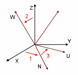
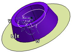
Euler angles: Defines an axis system using three angle values.
- Angle 1 (= X, N): Rotation about the Z axis transforming vector X into vector N.
- Angle 2 (= Z, W): Rotation about vector N transforming the Z axis into vector W.
- Angle 3 (= N, U): Rotation about vector W.
-
-
Optional: Right-click the Origin box and select
Insert Wireframe > Create Endpoint from the context menu to specify an end point of an element as origin.
-
Optional: Select a line as input for the X
axis.
The X axis becomes collinear with the line. The other directions are automatically computed if they are not defined.
-
Optional: Click the Y axis.
The Y axis is reversed.
Tip: You can also select Reverse next to the Y axis box to reverse its direction. -
Optional: Clear the Current check box.
The created axis system is not defined as the active axis system. Instead, the absolute axis system becomes the current axis system.Note: By default, this check box is selected. You can change the default setting in Me
 > Preferences > :
- In the Standard Definition dialog box, select Category: 3DModelingDefaultValues and in the Standard area.
- Select the required default setting in the Current list .
Notes:
- You can use the Shift key while creating the axis system to select the implicit elements belonging to the axis system. For more information, see Generative Shape Design User's Guide: Selecting Implicit Elements.
- There is associativity between the feature being created and the current local axis system. Therefore, when the local axis system is updated after a modification, all features based on the axis direction are updated as well.
- The display mode of the axes is different depending on whether the three-axis system
is right-handed or left-handed and current or not.
Right-handed + Current Right-handed + Not current Left-handed + Current Left-handed + Not current Solid 
Dashed 
Dotted 
Dot-dashed 
 .
.
 in the