-
From the Volume section of the action bar, click
Shell
 . .
- In the Faces to remove box, select the face(s) to be removed.
The Support Volume box is filled with the volume owning the
selected face. 
-
In the Inside thickness box, enter the value or use the arrows to change the thickness value.
- Click OK.
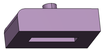
The feature is shelled: the selected face is left
open.  - Double-click the shell to edit it.
-
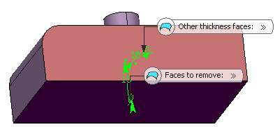
In the Other thickness box, select a face.
- Double-click the thickness value displayed on this face.
- Enter a value in the dialog box that appears and click
OK.
The length between the selected face and the shell is now 10mm.  -
Select the Smoothing mode.
| Option | Description |
|---|
| None |
No smoothing is applied. This is the default option. The Max deviation and Constant thickness boxes are disabled. |
| Manual |
Lets you enter a maximum deviation. The default value is 0.1 mm. The Constant thickness box can be selected to apply a constant thickness. |
| Automatic |
Smoothing is applied automatically. The Max deviation box is dimmed. However, the Constant thickness box can be selected to apply a constant thickness. |
- Click OK.
For more information, see 3D Modeling: 3D Modeling Core: Part Design User's Guide: Creating Shells.
|