Measuring Inertia in the Context of a Representation

You can measure inertia in the context of a representation. The resulting measures are stored in parameters.


Before you begin: Open a representation.
  1. From the Tools section of the action bar, click Create an Inertia Measure .
    • The Measure Inertia dialog box appears.
    • The Measure Item cursor replaces the default cursor when hovering the mouse over a measurable item.
  2. Click the PartBody.


    Important:
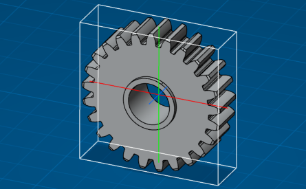
    • An inertia axis system is displayed:
      • The first moment marked M1 is identified with a red axis.
      • The first moment marked M2 is identified with a green axis.
      • The first moment marked M3 is identified with a blue axis.

      The inertia axis center is the center of gravity of the selected element.

    • A bounding box is displayed around the selected element parallel to axes.
    • A MeasureInertia geometrical set is created, containing a MeasureInertia object with inertia information as parameters.

      three contextual commands are associated with the MeasureInertia object:

      • Change Geometrical Set...: moves the inertia object into another geometrical set.

        See Managing Geometrical Sets.

      • Reset Properties: resets inertia graphical properties.
      • Recompute Inertia: computes again inertia data.

        This command is mandatory when a material associated with the analyzed geometry is modified.

    The Result tab content is updated.

  3. Click OK in the Measure Inertia dialog box.

When you create a measurement, it is in the active state by default. You can activate or deactivate single, or multiple measurements inside a part:

  • To deactivate the measurement, right-click the measurement, and select Deactivate. A mask appears in the specification tree for an inactive measurement.
  • To activate the measurement, right-click the measurement, and select Activate.

The Activate and Deactivate options are available for all types of measurements like measure between, measure item (point, edge, surface, and volume) and measure inertia features inside the part. You can prevent unnecessary updates from users by deactivating the measurements.

When you deactivate a measurement, it is not updated when the geometry of the part is modified and updated. When you activate the same measurement, it is updated according to the updated geometry that is linked with it.

An invalid mask appears on the measurement in the specification tree if you:

  • Activate a measurement that has a broken link.
  • Activate a measurement that corresponds to a deactivated linked geometry.
Note: You can measure the canonic polyhedral surface geometries such as plane, cylinder, cone, and sphere.