-
From the Geometry section of the action bar, click Curve Smooth
 .
.
- In the Curve to Smooth box, select the curve to be smoothed.
Important: - You cannot select a sub-element as curve to be smoothed. This is to prevent any confusion with possible elements to freeze, which can only be sub-elements. If you wish to select the sub-element of a curve, use the Extract command and select the extracted feature as element to be smoothed.
- You can select several input curves. In this case:
- The options on the Parameter and Extremities tabs are applied to all input curves.
- On the Freeze tab, you cannot select sub-elements to be excluded from the smoothing operation. Previously selected sub-elements will be removed from the list when adding further input curves to a single selection.
- If a support surface is selected, it must contain all input curves. Topology simplification will be applied to all input curves.
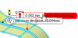
On the curve are displayed texts indicating its discontinuities before smoothing and the type of discontinuity (point, curvature, or tangency) and their values.
These values are expressed in the following units:
- For a point discontinuity: the unit is the document's distance unit (mm by default).
- For a tangency discontinuity: the unit is the document's angular unit (degree by default).
-
For a curvature discontinuity: the value is a ratio between 0 and 1 which is defined as follows:
if ||Rho1-Rho2|| / ||Rho2|| < (1-r)/r where Rho1 is the curvature vector on one side of the discontinuity, Rho2 the curvature vector on the other side, and r the ratio specified by the user; then the discontinuity is smoothed.
For example, r=1 corresponds to a continuous curvature and r=0.98 to the model tolerance (default value). A great discontinuity will require a low r to be smoothed.
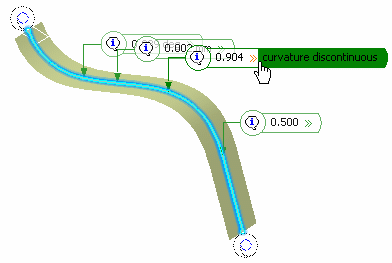
-
Click Preview to display the curve discontinuities that
are still present after the smoothing operation, and whether they are within or
outside the threshold values (yellow or red flag).
The value and location of the Maximum deviation between the curve to be smoothed and the smoothed curve are displayed in the work area.
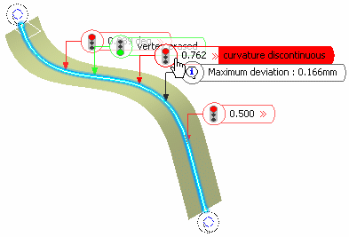
In the example, from top to bottom, once the curve is smoothed:
- The tangency discontinuity is still present.
- There is no more discontinuity, the point discontinuity is corrected.
- The curvature discontinuity still is present, even though it is slightly modified (different In and Out values).
- The curvature discontinuity still is present and not improved at all.
Basically:
- A red box indicates that the system could not find any solution to fix the discontinuity while complying with the specified parameters.
- A yellow box indicates that some discontinuity has been improved, where there was a point discontinuity there now is a tangency discontinuity for example.
- A green box indicates that the discontinuity no longer exists; it has been smoothed.
- Optional:
In the Tangency threshold box, modify the value that is the tangency discontinuity value above which the curve is smoothed.
If the curve presents a tangency discontinuity greater than this threshold, it is not smoothed.

- Optional: Select the Curvature threshold check box to set curvature discontinuity value above which the curve is smoothed.
- Optional:
In the Maximum deviation box, enter the deviation value to set the allowed deviation between the initial curve and the smoothed curve.
Therefore, the resulting smoothed curve fits into a pipe which radius is the maximum deviation value and the center curve is defined by the selected curve.
- Optional:
Select one of the Continuity options, i. e. the correction mode for smoothing, by checking either:
- Threshold: default mode. The tangency and curvature thresholds options are taken into account.
- Point: no point discontinuity should remain. There is no point discontinuity in our example.
-
Tangency: no tangent discontinuity should remain. The tangency threshold option is not taken into account, it is grayed out and the defined value is ignored.
-
Curvature: no curvature discontinuity should remain. The curvature threshold option is not taken into account, it is grayed out and the defined value is ignored.
You notice that there is no discontinuity any more:
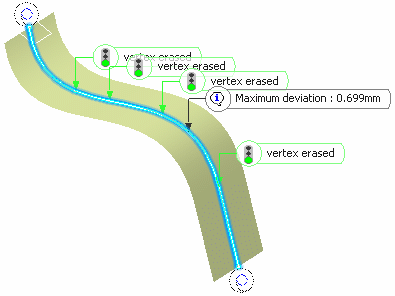
In case tangent or curvature discontinuities remain, an error message is issued.
- When a curve is curvature continuous and you try to smooth it, a warning message informs you that there is no discontinuity to smooth. Nevertheless, you can still improve the curve smoothing by clicking on Preview or OK in the Curve Smooth Definition dialog box.
- The following options are grayed out when smoothing a curve that is curvature continuous: both Tangency and Curvature Thresholds, all the Continuity options and the Freeze tab.
- Optional:
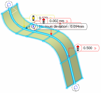
You can select a surface on which the curve lies. In this case the smoothing is performed so that the curve remains on the Support surface. This ensures that the maximum degree of smoothing is limited by the support surface's level of discontinuity.
-
Click the Freeze
tab and select sub-elements of the curve that
should not be smoothed.
These sub-elements can either be vertices or edges. In case of a vertex, the local neighborhood remains unchanged, thus keeping the discontinuity.
Click the Remove button to remove a single sub-element or a set of sub-elements.
Important: - External elements cannot be selected as sub-elements.
- Freeze is not supported in case of multi-selection.
You now set continuity conditions on the resulting smoothed curve for each extremity with regards to the input curve. As a comparison basis, the continuity condition was previously always curvature: the output curve had the same extremity points, tangencies and curvatures as the input curve.
-
Click the Extremities
tab and define the continuity conditions at
each curve's extremity.
- Curvature (by default): extremity point, tangency and curvature are the same.
- Tangency: extremity point and tangency are the same (curvature can be different).
- Point: extremity points are the same (tangency and curvature can be different).
You can also right-click the icon at the curve's extremity and choose one of the following options. You can sequentially move from one condition to the next one by clicking on the icons.


Important: The Point and Tangency conditions can only be successfully applied if the Maximum Deviation is larger than 0.005mm. Note that these extremity conditions do not affect closed curves. -
Click the Visualization
tab to define the way the messages are
displayed on the smoothed element.
You can choose to see:
- All: messages indicating where the discontinuity remains (red box) as well as those indicating where the discontinuity type has changed, or allows smoothing.
- Not corrected: only the messages indicating where the discontinuity is not corrected and remains.
- None of the messages.
- Display information interactively: only the
pointers in the geometry are displayed, above which the text appears
when passing the pointer.
- Display information sequentially: only one
pointer and text are displayed in the geometry, and you can sequentially
move from one pointer to the other using the previous/next buttons.

The Topology simplification option automatically deletes vertices on the curves when the curve is curvature continuous at these vertices, thus reducing its number of segments.
When it is the case, the displayed text indicates: Out: vertex erased to inform you that a simplification operation took place. This text is also displayed when two vertices are very close to each other and the system erases one to avoid the creation of very small edges (i.e. shorter than 10 times the model tolerance) between two close vertices.

Important: - This option is selected by default. It is grayed out when there is only one edge (that is when there is no vertex) on the curve.
- Note that it does not delete the closure vertex of the curve.
- In case of closed curves, the closure vertex may be modified. The chosen vertex corresponds to the least continuous vertex if a smoothing would be performed without topology simplification.
-
Click OK.
Tip: When smoothing a curve on support that lies totally or partially on the boundary edge of a surface or on an internal edge, a message may be issued indicating that the app found no smoothing solution on the support. In this case, you must enter a Maximum deviation value smaller than or equal to the tolerance at which two elements are considered as being only one (0.001mm by default) to keep the result on the support.