Cardiac Tissue Fiber Orientations | ||
| ||
As shown in the figure below from Holzapfel and Ogden, the fiber orientations associated with the structures in the heart are complex due to:
- The complex organic geometry of the heart
- Orientations changing across the surface of the heart
- Orientations changing through the thickness of the heart wall
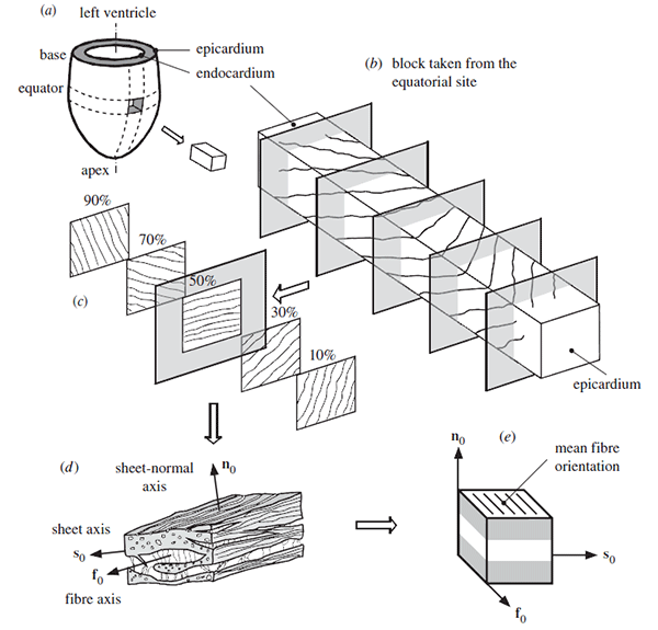
For the atria and ventricles, local material orientations are defined as a Discrete Field in Abaqus/CAE.
This methodology requires that a separate orientation be defined at the centroid of each element. The fiber angles, in the ventricles are approximately equal to –60° on the epicardium and +60° on the endocardium as shown in Streeter et al., which is consistent with Genet et al. The fiber orientations in the atria (as well as the superior vena cava, aortic arch, and pulmonary trunk) were approximated using Figure 20 in the euHeart Final Project Report. The model includes three Discrete Field definitions (named R_Atrium, L_Atrium, and Ventricles).
For the SVC, aortic arch, and pulmonary trunk, local material orientations are defined using the part geometry instead of a Discrete Field, since they are essentially tubular surfaces. For these regions, the material normal direction corresponds to the geometric surface normal, and a geometric edge is used to define either the local sheet or fiber direction.
The fiber orientation (as shown in the figure below)
can be visualized by running a datacheck on the mechanical model and examining
the output database (ODB) file in
the Visualization module.
The figure shows epicardial fiber orientation in red, endocardial fiber
orientation in blue, and the average fiber orientation in green.

If you need to redefine the initial fiber orientations for the atria, ventricles, or any portion thereof, as a result of modifications made to the model geometry (such as after creating a partition in the ventricle that is then remeshed), refer to the plug-in described in Remap the Initial Fiber Orientations. You can also override the orientations, in which case you must specify the orientation at the centroid of each element. Since the fiber orientations for the SVC, aortic arch, and pulmonary trunk are defined on the geometry, they will be regenerated automatically during remeshing; no special user intervention is required. However, you can easily change the fiber angle for these parts, if required.