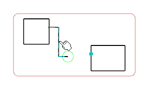
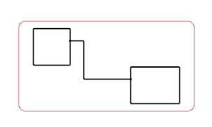
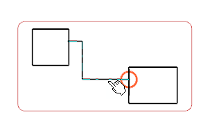
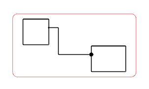
You can connect symbols in a diagram view.
Before you begin: Two symbols with ports are instantiated in a diagram view.
-
From the
Layout section of the action bar, click
Connect Symbols
 .
.
-
In the diagram view, click one of the following elements:
- A connection point on the first symbol (1)
- A symbol (2)
Note:
If the Lock pins multiple
representations is selected in
, the Available Ports for Mapping
dialog box only displays pins which are not represented in a drawing.
For more information, see Native Apps Preferences
Guide: Schematic.
-
Do one of the following actions according to your selection in
Step 2:
| Action Done in Step 2
|
Action to be Done
|
Result
|
| 1
|
Click a connection point on the
second symbol.
|
The two symbols are
connected. The connection points are linked with a connection.
|
| 2
|
Select a port in the Port Mapping
Available Ports for Mapping.
|
| 2
|
Click
Graphical Connect on the
context toolbar
and select standalone connection point or component.
Note:
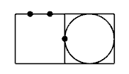
If a component is selected, an
unmapped connection point is created at the selected position.
|
A graphical connection is created
between the connection points created on the first and second components.
|
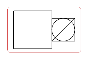
Note:
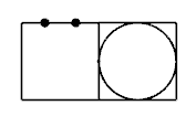
When two symbols are connected, the second symbol
can be rotated so the connection points of the two symbols have opposite
directions.
For more information about port and connection point creation
during a connection, see
About Route Between Symbols.

