-
From the Layout section of the action bar, click Manipulate Symbols
 . .
The App Options panel appears.
Note:
The mode selected to modify the symbol position remains active when selecting Manipulate Symbols again.
-
Select the symbols to be mirrored.
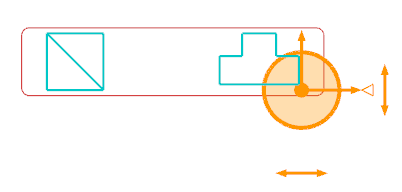
The Manipulation Options Chooser dialog box appears. The handle appears and the selected symbols are highlighted.
 - To modify the center of the rotation, drag the middle point of the compass to the desired location.
-
Select one of the following options to create object instances or new object references in the tree:
- Instantiate: The references of all the selected objects are
instantiated under the same context as that of the selected objects. Modifications on
the orientation or the position are applied to the instantiated objects.
- Duplicate: The references of all the selected objects are duplicated
under the same context as that of the selected objects. Modifications on the orientation
or the position are applied to the duplicated objects.
- Business Rule: The references of all the objects which can be duplicated or instantiated are defined through the Schematic_ComputeInstantiateDuplicateOptionsRule business logic. This business logic is associated with the Rule for Instantiate/Duplicate Option resource.
Notes:
- If symbols from different systems have been selected in Step 2, the
Instantiate and Duplicate options
are not available. For the Business Rule option, the
List_Context_Change_Options parameter must be set to 1. - When no business rule is associated with the Rule for Instantiate/Duplicate Option resource, the Business Rule option is not available.
-
If you have selected the
Duplicate option, enter a prefix for the duplicated references names.
-
Choose along which axis the new symbols are created:
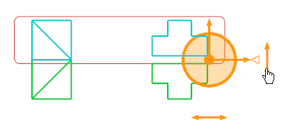
- Click the y-axis manipulator to translate the objects along the y-axis.
- Click the x-axis manipulator to translate the objects along the x-axis.
- Click OK.
When the Instantiate or Duplicate option is selected, the Manage Line ID dialog box appears and displays the following information: - Select New Group column: the line ID to which the instantiated objects are transferred to (target line ID).
- Existing Group column: the line ID to which the selected objects belong (original line ID).
- Remaining columns: the attributes information of the original line ID (line type, standard, size and specification).
- In the Select New Group column, right-click the line ID and select one of the following options:
- Select Line ID: The Select Line ID panel opens with the list of available line IDs. Double-click the line ID to which the instantiated objects are to be transferred.
- New Line ID: The Create Line ID panel opens.Create a new line ID.
- None: The target line ID is switched to unset.
- Reset: The line ID is reset to the original line ID.
- Click OK to validate the new symbols.
Note:
Clicking Cancel instantiates the objects without assigning them to any line ID.
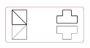
In the diagram view, the objects are reversed or mirrored according to the selected type of manipulation. In this example, the initial symbols have been instantiated, and then mirrored along the x-axis.

In the tree, the instantiated objects are assigned to the selected target line ID.
|
 .
The App Options panel appears.Note: The mode selected to modify the symbol position remains active when selecting Manipulate Symbols again.

