Creating a Matching Constraint and Modify Continuity Constraints | ||||
| ||||
-
From the Modification section of the action bar, click Matching Constraint
 .
.
-
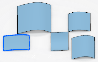
Select the edge of the source surface to be matched.
The source surface edges are now highlighted in blue.
-
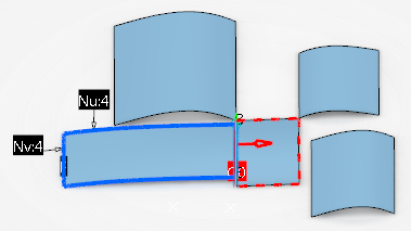
Select the reference edge of the target surface.
The target surface edges are highlighted in red dashes.
Note: If one of the Both options is selected, the edges of both source and target surface will be highlighted in blue.If Partly
 is selected, the letters B and E indicate
the beginning and the end of the part of the edge to be matched. At each end, a green
manipulator is available allowing you to modify the part to be matched by moving it
along the edge.
-
Click Apply.
The surface is modified according to the settings.
-
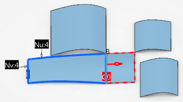
Clear Partly and click Apply again.
The source edge matches completely the target edge.
-
Click OK.
Important: Clicking OK does not perform the Apply operation. -
Create several constraints.
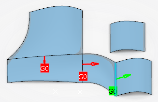
-
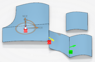
Right-click the G0 (point) continuity tag and change the
continuity type to G2 (curvature).


-
Right-click the G2 continuity arrow and select Invert
Source/Target to reverse the direction of the constraint.
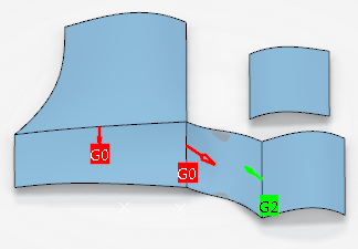
-
Right-click the G0 continuity and deactivate it.
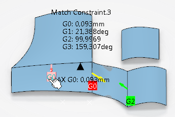
The arrow color indicates the constraint's activation status:
- Green or red: Activated.
- Yellow: Deactivated.
The continuity color indicates whether the continuity is met:
- Green: The continuity is met.
- Red: The continuity is not completely met.
Move the cursor over a continuity to display the deviation values for all continuity types and the position with the maximum G0 deviation.
Note: In Me > Preferences > App Preferences > 3D Modeling > Styling
> ICEM Shape Design, Tolerance
tab,
Continuity Tolerances section, you can specify tolerances
within which continuity deviations are allowed.
 -
Select a surface and click Control Points
 to display the control points and mesh lines on the surface, allowing you to dynamically modify them.
When you deform the source surface, the neighboring constraints are updated automatically.
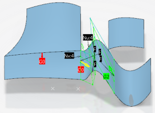
- Click Cancel in the Control Points dialog box.
-
Select a surface and click In Model or on Perch
 in the Robot
context menu to switch the compass from the perch to the selected surface.
-
Use the Robot to move the surface.
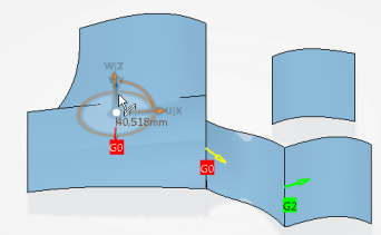
All the constraints are updated accordingly, except the deactivated constraint.