Analyzing Using Inflection Lines | |||||
|
| ||||
-
From the Analysis section of the action bar, click Inflection
Lines
 .
.
-
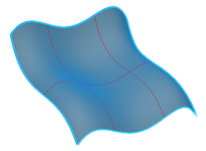
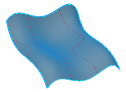
In the Local Plane Definition section, select
Parametric.
The inflection lines are displayed on the surface.
-
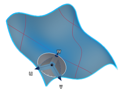
Select Robot Plane.
-
Drag the Robot onto the surface.
The Robot base is orientated in the same plane as the local tangent to the surface and the inflection lines are updated.
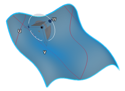
-
Drag the Robot to a new position on the surface.
In the new position, the orientation of the Robot base plane has changed, therefore the inflection lines are updated on the surface.
- Creating and retaining inflection lines on a surface is especially useful to determine at which points the curvature of the intersection between the cutting planes and the surface is 0.
- When you use this command with the Inflection area option of the Surfacic Curvature Analysis command, note that the inflection lines are always created within the green areas.
- When you select the geometrical set as an input in the tree, all the elements included in this geometrical set are automatically selected.