Creating Isoparametric Curves on Surfaces | ||||
| ||||
-
From the
Curve section of the
action bar, click Isoparametric Curve
 .
.
- Support defines the isoparametric curve support, you
can:
- Select any existing surface as support.
- Right-click in the Support box to create the
surface or select multiple surfaces using the stacked commands from
the context menu.
For more information, see also Extracting Elements, Creating Extruded Surfaces, and Joining Curves or Surfaces.
- Point defines the isoparametric curve point.
- Indicate the point by clicking at the desired location on the support.
- Right-click the Point box to create the point
using the staked commands from the context menu.
For more information, see also Creating Points, Creating Intersections, and Creating Projections.
- Direction defines the isoparametric curve direction.
- Select the direction by clicking a geometrical element.
- Right-click the Direction
box to create the direction using the staked
commands from context menu.
For more information, see also Creating Lines and Creating Intersections.
- Swapped Cells displays the cell where the
isoparametric propagation direction has been swapped from the nearest
isoparametric propagation direction to the farthest isoparametric
propagation direction. This functionality makes sense in case of multiple
surfaces support.
 Swapped Cells List: Displays the list of swapped
cells in a dialog box.
- Support defines the isoparametric curve support, you
can:
-
Select Join.1 as curve support.
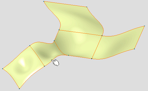
The Point field is highlighted in the Isoparametric Curve dialog box. The isoparametric curve is previewed on the surface when you move the cursor.
-
Click to indicate where to create the isoparametric
curve.
- The isoparametric curve is pre-created, a handle is displayed. In case of multiple surfaces support, the selected surface is the reference cell.
- You can move along the curve using the arrows of handle. In case of multiple surfaces support you can only move the handle inside the reference cell.
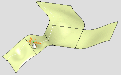
A context menu is available when you right-click the handle:
- Edit: This option allows you to define the isoparametric curve according to its parameters.
- Keep this point: This option allows you to create the point where you clicked.
- Swap UV: This option allows you to swap U and V
parameter values. This option is also available in the Isoparametric
curve dialog box when you click the Swap
UV

-
Select Swap UV from the context menu.
The isoparametric curve parameters are swapped.

- Re-select Swap UV from the context menu.
-
Select Keep this point from the context menu.
The point is created.
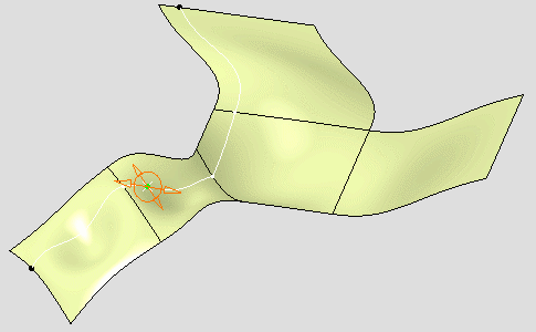
The Point and Direction fields are filled according to the selection in the Isoparametric Curve dialog box. Point and Direction are editable from the Isoparametric Curve dialog box using icons at the right of each field: Point: Click this icon to edit the
point. See Creating Points.
 Line: Click this icon to edit the
line. See Creating Lines.
-
Select Edit from the context menu.
The Tuner dialog box appears.
-
Select Relative check box in the
Tuner dialog box.
The relative origin of the curve is displayed on the curve support.
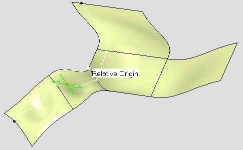
The Tuner dialog box is modified:- True Length option is displayed.
- Reset Origin button is displayed.
-
Click Reset Origin in the Tuner
dialog box.
The relative origin of the curve is reset from the curve point.
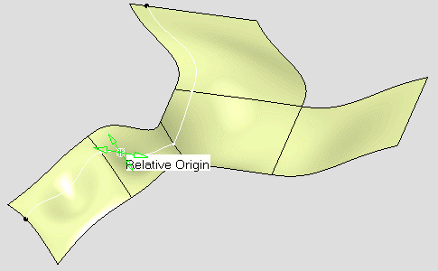
The Tuner dialog box displays the new origin values. - Click Close in the Tuner dialog box.
-
Select the surface as shown.
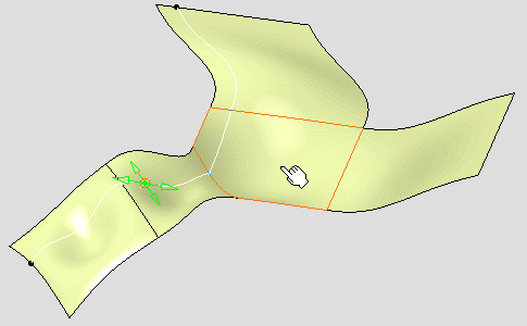
The isoparametric propagation direction has been swapped from the nearest isoparametric propagation direction to the farthest isoparametric propagation direction in the selected cell.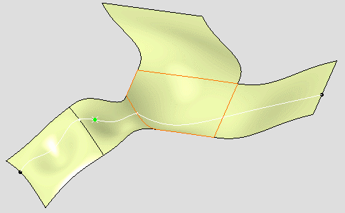
The selected surface has been added to the Swapped Cells field. -
Click Swapped Cells List
 The Swapped Cells List dialog box appears. You can Remove or Replace the selected elements inside this dialog box.
 - Click Close in the Swapped Cells List dialog box.
-
Click OK in the Isoparametric curve
dialog box.
The isoparametric curve is created.
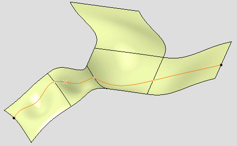
The Isoparameter.1 object is created in the tree.A point and line have been created:
- The point corresponds to the cursor location when you define the curve.
- The line corresponds to the curve orientation when you define the curve.
The Swap UV parameter contains the information indicating that the curve has been swapped.