Defines which criteria to choose as input for the fillet creation.
In the Radius Parameters area, the display and availability of the options changes according to the selected
fillet type.
The following fillet types are available:
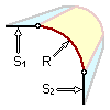
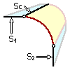
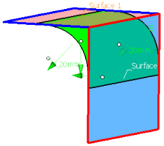
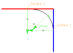
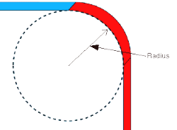
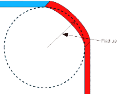
2 Supports + radius
Defines the fillet surface by two supports and the Radius.
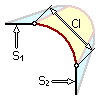
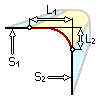
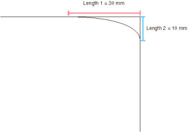
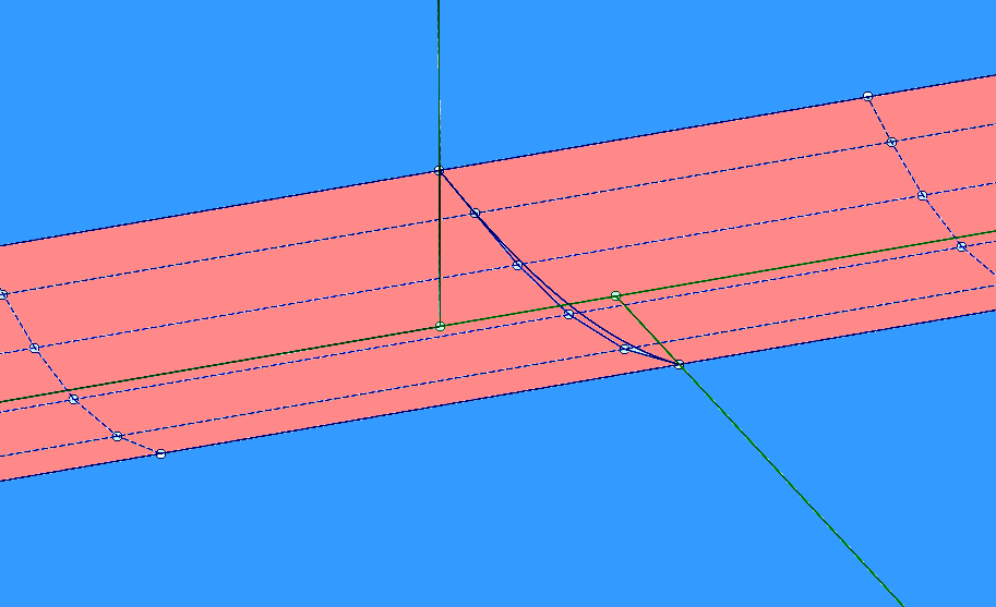
2 Supports + chord length
Defines the fillet surface by two supports and the chord length.
The chord length is the distance between both edges of the fillet surface lying on the
supports.
2 Supports + 1 support curve
Defines the fillet surface by two supports and a support curve used as fillet surface
edge.
The radius value derives from the support curve.
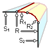
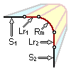
2 Supports + 3 radii
Defines the fillet surface by two supports, the Radius as well as two lead-in radii ( Lead-in radius 1/2 ).
Depending on the selected radii, you can create an asymmetric fillet surface.
Note:
To
be able to create a fillet surface with three different radii, both lead in radii must
not be larger or smaller than the first radius, but one lead in radius must be larger
or smaller than the other one.
2 Supports + 2 chord lengths
Defines the fillet surface by two supports and two chord lengths.
The chord length is the distance between the theoretical intersection point of the arc
tangents and the fillet surface edge on the corresponding support.
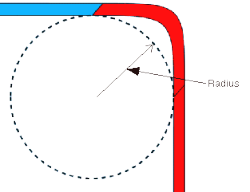
2 Supports + true minimum radius
Defines the fillet surface by two supports and the true minimum radius.
Using the true minimum radius guarantees that the radius in the fillet curve does not
fall below the specified value while keeping the continuity set.
2 Supports + true minimum radius with G1 continuity
2 Supports + true minimum radius with G2 continuity
Supports
Support 1 and 2 - Surface 1/2
Selects sets of surfaces as supports. If two or more support surfaces are selected,
the normal direction of the first selected support surface is used.
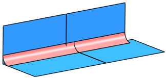
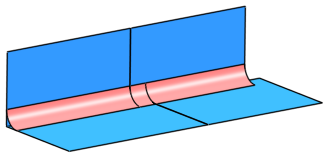
Trim Support 1/2
Trims the support surfaces at the corresponding edges of the fillet surface.
Support 1 and 2 - Curve
Selects sets of curves as supports.
Two fields are available for the curve input.
You can select the following element types:
Defines the lead-in radius as an arc with tangent (G1) or curvature (G2)
continuous transition to the original support surface. The radius value defines
the point at which the lead in radius starts.
Selects for each side a continuity from G0 to G3 between fillet surface and
supports.
The minimum order of the fillet surface in arc direction depends on the selected
continuity. The order can be increased using the options in the
Approximationtab.
Mid radius
For the middle of the arc can be defined a mid radius different from the radius.
The continuity is kept when the mid radius is modified.
The mid radius is applied along the centerline of the radius value.
7
This option is only available if Form factor is cleared.
Form factor
With this option, you can determine whether the fillet shall be more flat or more
copped. The continuity to the supports remains unchanged.
Values smaller than 1 create flat fillets, values higher than 1 steep fillets.
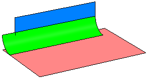
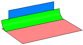
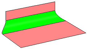
Form factor cleared
Form factor 0.5
Form factor 2.0
This option is only available if Mid radius is cleared.
Options
Parametrization
Specifies how the parametrization of the fillet surfaces is influenced.
The
following options are available:
Support 1 / Support 2
Takes the parametrization from the 1st or 2nd set of
support surfaces, i. e. the segment boundaries of the support surface 1 or 2
determine the segment boundary of the created fillet.
Both Supports
Takes the parametrization from both sets of support surfaces or curves.
At each segment boundary of the support surfaces, a segment boundary is
inserted in the fillet surface. In this case, very small segments may eventually
be created.
Stitch
If the distance between two segment boundaries of the support surfaces is
smaller than the tolerance specified in the Tolerance
box, only one segment boundary is taken either from surface 1 or from surface 2.
Average
If the distance between two segment boundaries of the support surfaces is
smaller than the specified Tolerance, only one segment
boundary is inserted in the middle between the segment boundaries of the support
surfaces.
Rip
If the distance between two segment boundaries of the support surfaces is
smaller than the specified tolerance, only one segment boundary is inserted.
The segment boundary is G0 continuous to the segment boundaries of the
underlying surfaces. The tolerance value has the same meaning as for the
Stitch and Average options. Segment boundary with G0 continuous transitions independent from the
continuity support setting.
RipMatch
If the distance between two segment boundaries of the support surfaces is
smaller than the specified tolerance, only one segment boundary is inserted.
At the fillet segment boundaries, the continuity specified for
Continuity support 1 and Continuity support
2 is used. The tolerance value has the same meaning as for the
Stitch and Average options. Segment boundary with G2 continuous transition (Continuity support 1:
G2) at support surface 1 and G1 continuous transition (Continuity support 2:
G1) at support surface 2
Tolerance
Only available for the parametrization options Stitch,
Average., Rip, and
RipMatch.
The initial segmentation of the fillet is increased until the tolerance is kept, i. e.
if the maximum distance between two segment boundaries of the support surfaces is
smaller than the tolerance, only one boundary is inserted instead of two, depending on
the selected parametrization.
Relimitation
Only active if Extrapolate is selected.
The fillet surface
can be trimmed in two different ways. The fillet surface is the basic surface for the
trim operation.
Trim Face
The basic surface remains unchanged.
Trim Approx
The basic surface changes. The result is not a face.
Assure cont.
In the resulting geometry, the specified continuities shall be respected within the
tolerances specified in Me > Preferences > App Preferences > 3D Modeling > Styling> ICEM Shape Design , Topologytab.
In configurations not allowing the compliance of all continuities - especially for G2
fillet surfaces, this option keeps the continuity at the different transition types with
the following priority:
transition A: transition between fillet ribbon and support surfaces within the
specified tolerance, then
transition B: transition between elements of the fillet ribbon within the
specified tolerance, then
transition C: transition on fillet traces within the specified tolerance.
Exception: G1 continuity is very important for the transition types A and B. If it is
impossible to have G2 for transition type A and G1 for transition type B, G1 has
priority for both transition types A and B.
Extensions
Extrapolate
If the connecting edges of the support surfaces have different lengths, the
fillet surface can be extended to the exterior edges of the support surface with
the larger extent. The extrapolation can be activated for the start and end edge
curves of the fillet.
Extrapolate cleared
Extrapolate Start selected
Extrapolate Start and
End selected
Match end
The start and end curve of an extrapolated fillet surface (
Extrapolate selected) can be matched to the exterior edges of
the support surfaces creating a tangent continuous transition.
Match end Start selected
Match end Start and End
selected
Match end Start and End
selected with trimmed support surfaces
More Info
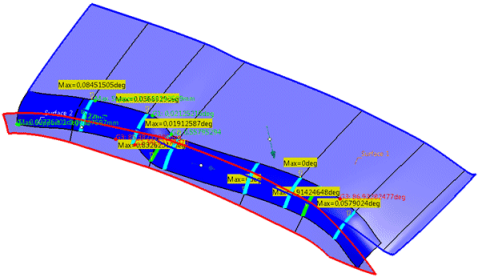
Displays deviations and output results.
Display
Displays values in the work area.
U+V
Displays the UV vectors of curves and surfaces.
Apply Modes
Defines the update mode of the active feature while editing it.
Dynamic
Feature update occurs dynamically when moving handles or editing parameter
values by sliders in the dialog box.
This option is not available for each command.
Static
Feature update occurs only after releasing the handle.
Preview
Displays a preview when geometry is modified by means of the handle and LMB pressed. The
original geometry remains unchanged. Feature update occurs only
after releasing the LMB.
This option is not available for each command.
None
Feature update occurs only after selecting Apply.
Deviation
Support 1/2
Indicates the maximum deviation of the fillet surface from the support
surfaces.
Internal
Indicates the maximum G1, G2, and G3 deviation between the different created
fillet surfaces.
Output Result
Max. order
Indicates the maximum order of the result created in both U and V.
Max. segments per cell
Indicates the maximum number of segments created in U and V direction.
No. of cells
Indicates the number of cells created in the result.
 2 Supports + radius
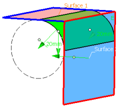
 2 Supports + chord length
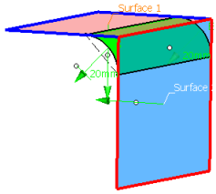
 2 Supports + 1 support curve
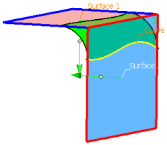
 2 Supports + 3 radii
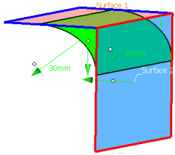

 2 Supports + 2 chord lengths
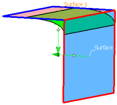
 2 Supports + true minimum radius
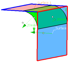

 Trim Support 1/2


 Trim Face
  Trim Approx
  > Preferences > App Preferences > 3D Modeling > Styling
> ICEM Shape Design , Topology
tab.
> Preferences > App Preferences > 3D Modeling > Styling
> ICEM Shape Design , Topology
tab.