General Information

|
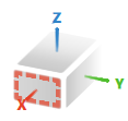
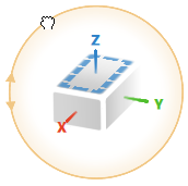
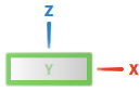
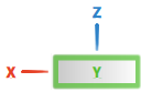
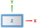
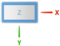
The model coordinate axes and planes are represented by colors, according to the RGB principle (red=x, green=y, blue=z). | |
|
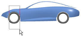
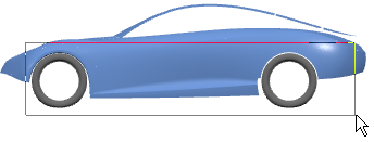
A dashed frame indicates the active V-Nav plane. Each V-Nav plane represents a standard OmniPlane. If no frame is displayed, a user-defined OmniPlane is active. | |

|
A continuous frame indicates the coincidence of the active V-Nav plane with the view plane. | |

|
Circles around the labels of the x-, y-, and z-axes indicate that the current view is a standard view. | |
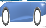
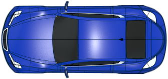
preselected front plane 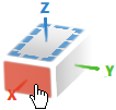 |
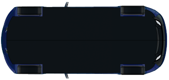
preselected rear plane 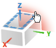 |
Planes are highlighted in preselection mode. |
 |
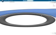
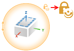
The red, green, and blue circles around the tool indicate the rotation plane of the model coordinate system. | |
 |
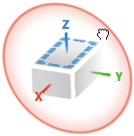
The orange circle indicates the view plane for rotating around the view normal. | |

|
|
The highlighted orange circle with a lock symbol indicates that the VNav tool is locked in the current view plane.
Click the circle to switch between the lock modes. Notes:
|


 + click left
  ), and
  ). With