-
Create a blend surface as described before.
By default, a blend
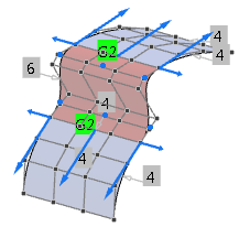
surface is created with G2 continuity at Rail
A and Rail B. The order perpendicular to
the rails is 6 as three control point rows are necessary to keep G2
continuity.
-
In the Display section, select furtive display for Modifiable and Reference to display orders, continuities, and the control point mesh.

-
Select G1 continuity at Rail A
and Rail B.
The order is changed to 4 as only two control point rows are necessary to keep for
G1 continuity.
-
Select G1 in the Implied
line.
If no other direction is selected, the created G1 transition is aligned
to the z-direction of the model coordinate system. In the work area, an OmniPlane with the corresponding orientation appears.
-
Select Activate Transform
 in the Sculpt panel, select the OmniPlane
and modify its orientation. in the Sculpt panel, select the OmniPlane
and modify its orientation.
-
Select
Flange.
The flange angle is the angle between the cross tangents of the support and
blend surface. The continuity is set to G0 as higher
continuities cannot be kept if a flange angle is specified.
By default, the flange angle is set to 180deg which creates a G1 transition. Note:
Although the continuity is G1, G0 is still displayed in the work area if furtive display is selected.
-
Modify the Flange Angle by clicking the value and
entering another value or moving the slider.
-
Select
Draft.
Implied G1 continuity is created. In addition, you can define a draft
angle. The default value is 0deg, that is the draft direction is defined by the
current OmniPlane z-direction and provides the same result as Implied
G1. You can modify the OmniPlane orientation and the draft
angle in the same way as for Implied G1 and
Flange options.
|