You can use the Flow Control options to influence the
direction of the modified control point rows of the blend created surface.
Note:
The Linear Align and Edge
Align options have only effect if a higher continuity than G0 is used.
For higher continuities than G1 the control point rows are rectified.
Before you begin: Create a blend surface from input surfaces as shown
below.
Create a blend surface.
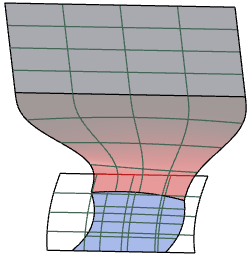
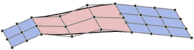
By default, the blend surface is created with the flow control option Free at Rail A and Rail B, that is the edge direction of the connecting edges of the blend surface is kept at the selected rail and rectified.
G1
G2
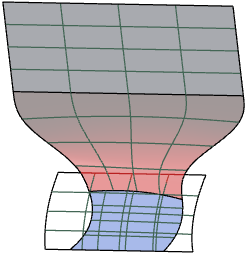
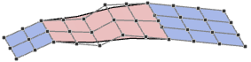
In the Flow Control section, select Linear
Align at Rail A and Rail
B.
The control point rows of the blend surface are aligned to the input surface at the selected rail.
G1
G2
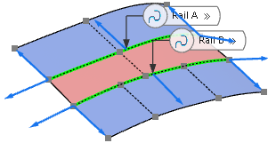
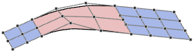
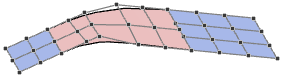
Select Edge Align.
The control point rows are aligned perpendicular to the connecting edge of the input surface at the selected rail.
G1
G2
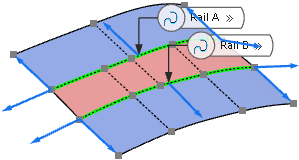
Align a blend surface to a face.
Create a blend surface from a surface and a face created with the OmniCut command.
With the default Linear Align setting, the blend surface is aligned to the input surface from which the face was created. The blend surface iso curves run in direction of the iso curves of the input surface at Rail B.
Select All Edges.
The blend surface is aligned to the face. The blend surface iso curves also run in direction of the iso curves of the input surface at Rail B, but are aligned to the direction of the edges at start and end of Rail A.
Change Edge Flow from Rail A to
Rail B.
The parameterization from the input surface is adopted at the selected edge.
Parameterization from Rail A
Parameterization from Rail B
Align the blend surface segmentation.
By default, the flow control aligns the segmentation of the blend surface with the selected rail. You can also align the segmentation with the other rail.
Open a 3D shape containing two joint surface clusters used as input geometry.
Create a blend surface and in the Geometry section of the OmniSurf panel, select Order V INP.
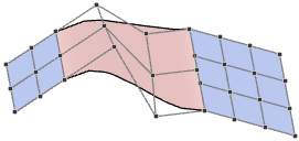
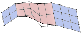
By default, the blend surface is created with a segmentation aligned with Rail A.
In the Edge Flow list, select Rail A+B.
The blend surface is created with a segmentation aligned with Rail B
Select Reverse to reverse the direction of the blend
surface at the selected rail.


 command.