About Matching

This section deals with basic concepts you should know before beginning with matching geometry.

Recommendation: For commands creating transitions between surfaces, use a minimum order of 6 to obtain optimal results.

This page discusses:

See Also
Matching Surfaces

General Information

In the domain of Class A modeling, one of the key features is the matching between several objects and boundaries (like surface-surface match, or curve-surface match etc.). In general, the matching function modifies the control points to achieve a certain geometric continuity at the matched boundary (edge or point).

However, for Class A modeling, we have scenarios where the matching must not change any control points but only report that the match is not fulfilled anymore. You can now handle this by the use of the ICEM Design Experience matching constraint feature. As the command specifies the matching and computes the result, the soft parametric options give control of how the matching shall react.

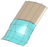
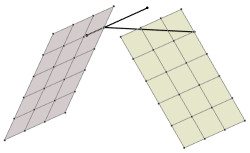
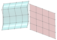
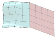
The first selected edge (surface matching) or point (curve matching) is the object (target) to be connected to the second selected reference object (source). When using Source-Target option, only the connected object is modified:

source (modified) target (unmodified)

OmniMatch Types

OmniMatch supports the following match types:

Match Type Required Input
First selection

(target = object to be connected

with shape modification)

Second selection

(source = reference object

without shape modification)

Surface Edge Surface Edge
Surface Edge Face Edge
Surface Edge Surface/Face Interior
Surface Edge Curve Interior
Curve Endpoint Curve Endpoint
Curve Endpoint Curve Interior
Curve Endpoint Surface Edge
Curve Endpoint Face Edge
Curve Endpoint Surface/Face Interior

Particular OmniMatch Parameters

Mapping
Only available for surface matching.
Controls which parameter on one edge is matched to which parameter on the other edge.
Exact
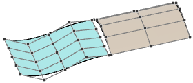
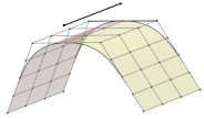
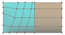
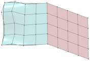
Adopts the parameterization of the reference surface, that is in case of equal order the control points coincide at the connecting edge.
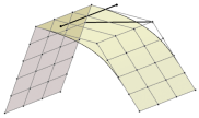
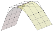
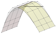
Input example:

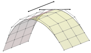
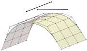
Results:


Exact G0


Exact G1


Exact G2


Exact G3

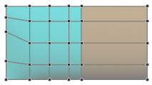
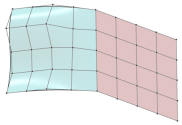
Arc Length
The connected surface keeps the arc length parameterization. The control point mesh and thus the surface is less modified.


Arc Length G0


Arc Length G1


Arc Length G2


Arc Length G3

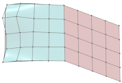
Project
For the connection is used as projection direction the shortest distance between each pair of opposite points on the connecting edge and reference edge.


Project G0


Project G1


Project G2


Project G3

Note: Project works best combined with the Partial Edge option based on the same projection.
(Modify) Orientation
These options define whether only the connected object or both, connected and reference object are modified.

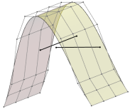
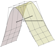
Input example:

Source-Target
Only modifies the connected object.

Free
Modifies the connected and reference object including the connecting edge or point.


Free G0


Free G1


Free G2


Free G3

Fixed
Uses a mean value for the connecting edge or point. If the transition is already G0 continuous, the modified edge/point is kept with higher continuities.


Fixed G0


Fixed G1


Fixed G2


Fixed G3

Extended Intersection
Computes an intersection of the tangents of both objects. If the transition is already G0 continuous, the modified edge/point is kept with higher continuities.


Fixed G0


Fixed G1


Fixed G2


Fixed G3

Persistent Orientation
Disable dynamic swapping
Disables any dynamic swapping of Source-Target during control point modification.
Swap
Swaps connecting (target) and reference (source) edge or point, respectively.
Note: This option is only available during creation procedure and not when editing the feature.
Direction: X, Y, Z, View, Object, Auto
Depending on the continuity, the target control points are moved when being matched to the source object. You can specify a direction to which the control point movement is fixed as far as this is possible in compliance with the continuity. This allows you to preserve the control points distribution in the normal plane of the selected direction axis.
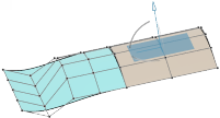
In the work area, the direction is represented by an OmniPlane handle, which you can also manipulate to modify the direction dynamically.
If nothing is selected when the Object option is active, the normal of the u,v-parameter plane of the source is used as direction.
For the Mapping and Partial Edge options and for matchings into the interior, the direction is used as projection direction.
Direction
Depending on the continuity, the target control points are moved when being matched to the source object. You can specify a direction to which the control point movement is fixed as far as this is possible in compliance with the continuity. This allows you to preserve the control points distribution in the normal plane of the selected direction axis.
Automatic
Computes the direction of the control point movement internally.
Attach To View
Sets the matching direction to the current view when the matching is recomputed, for example, after changing the continuity.
Fix Direction : X, Y, Z, View, Object, Auto
In the work area, the direction is represented by an OmniPlane handle that you can also manipulate to modify the direction dynamically.
If nothing is selected when the Object option is active, the normal of the u,v-parameter plane of the source is used as direction.
Auto corresponds to the Automatic option with the additional display of an OmniPlane.
For the Mapping and Partial Edge options and for matchings into the interior, the direction is used as projection direction.
Iso Curves
Only available for surface matching.
Usually, surface matching is computed directly on the surface control points. However, computation on iso curves is mathematically correct and results in better continuities. The resulting iso curves are then interpolated to provide the result surface.
Warning: The interpolation step may result in an irregular control point mesh.
Tangent Ratio
Only available for surface matching.
The mean value of the tangent ratio between all cross tangents is calculated and adopted.
Tangent Ratio cleared

Tangent Ratio selected

This option provides a better continuity for single matches between surfaces at the cost of a more rectified control point net.
Note: If several matches are computed next to each other, each match computes its own average tangent ratio. This destroys any continuity perpendicular to the computed match, even G0 continuity. Thus, the Tangent Ratio option should not be used for multiple matches next to each other.
Flow Control
Only available for surface and curve to surface matching.
Controls the direction of the modified control point rows or iso curves (see Iso Curves option).
For surface matching, you can specify the options separately for start and end of the connecting edge with a linear transition of the effect.
Note: The Linear Align and Edge Align options have only effect if a higher continuity than G0 is used. For higher continuities than G1, the control point rows are rectified.
Input Example:

Results with Continuity G1 and G2 and Mapping option Exact :
Linear Align
Aligns the control point rows of the connected surface to the reference surface.


G1


G2

Edge Align
Aligns the control point rows perpendicular to the connecting edge.


G1


G2

Free
Keeps the edge direction of the connecting edge, but rectifies it.


G1


G2

Special
Sliding
In case of a T connection, you can move the curve end point along the curve or edge of the target object using the handle displayed in the work area.
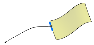
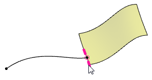
Only available with the following matching types:
  • Curve Endpoint - Curve Interior
  • Curve Endpoint - Surface Edge
  • Curve Endpoint - Face Edge
  • Curve Endpoint - Surface/Face Interior
  • Curve Endpoint - Surface/Face Interior
The following conditions must also be met:
  • Persistent Orientation option must be selected
  • The input geometry must allow a T connection.
  • The endpoint to be moved must be the source. Eventually use the Swap option to correct the selection order.