Analyzing Using Highlight | |||
| |||
-
In the
Analyze panel, click
Activate Analysis
 and
Highlight
 .
The model is displayed with the Default highlight analysis variant.
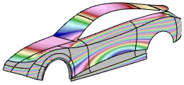
The Global/Local icon changes to blue
 indicating that you performed a global analysis on all elements that
are visible in the work area.
 -
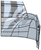
Select Projection: Cylinder and change to the front
view.
Option Description Beam Calculates the highlight lines from the light beam of a parallel light source. 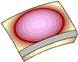
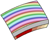
Cylinder Creates the highlight lines by reflecting stripes on the interior side of an imaginary cylinder around the geometry.
The cylinder axis direction is defined by the Direction option. The VNav axes define the direction.
-
Select the Black and White
 highlight variant.
Highlight Variant Description Default 
Default using medium values. 
Highlight 
Grayscale display of the highlight lines. 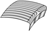
Colored 
Colored display of the highlight lines. 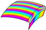
Black and White 
Black and white display of the highlight lines. 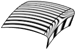
-
Increase the number of highlight lines with
Cycles.
20 Cycles 200 Cycles 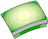
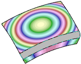
The highlight lines are projected from the interior side of an imaginary cylinder.
-
Change the Clip value to define the brightness or color
transition quality.
Clip 0 Clip 100 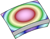

-
Change the Shine value to define the highlight line
width.
Shine 0 Shine 100 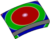
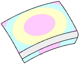
-
Click the Type: Shaded color button and select another
highlight line color.
Option Description Shaded Creates a shaded highlight result. Curve Creates curves as the highlight result. Curve can only be selected if Projection: Beam and Attached: Model are selected.
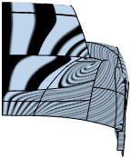
-
Select
Transparency for a transparent display.
-
Click
 to reset the settings to the defaults.
-
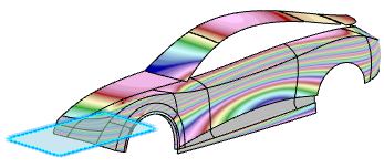
From the Surfacing section of the action bar, click OmniPlane
 .
.
-
Click
OK in the
Omni Plane panel.
A default OmniPlane is created.
-
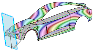
Select the
OmniPlane and click
Transform
 in the
Sculpt panel.
- Manipulate the plane using the robot.
-
Click Direction: Plane in the
Analyze panel.
You can also select the x-, y-, or z-axis.
Cylinder Direction X Cylinder Direction Y Cylinder Direction Z 
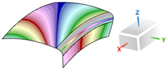
 The highlight lines are oriented in the OmniPlane normal direction.
-
Select some elements and click
 .
The elements are removed from the input geometry and the analysis is recomputed.
.
The elements are removed from the input geometry and the analysis is recomputed.The Global/Local icon changes to grey
 indicating that you performed a local analysis only on the selected
elements.
 -
Click
Global/Local
 to switch between the global and the local analysis.