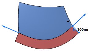
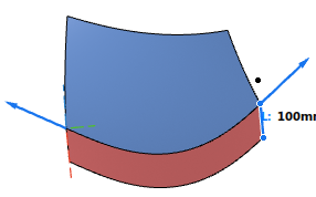
Using Explicit Controls on Flange Surfaces | |||||
|
| ||||
- Create a flange surface as described before.
- Select Flow Parallel.
-
Select Crowning and specify a draft angle unequal 0.
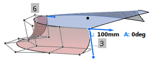
The flange surface is overcrowned and the basic order 2 in cross direction automatically increased to 3. -
Select Tubing.

By default, the flange surface is created as an open tubing surface with an angle of 90deg. The order in cross direction is increased to 6. -
Specify a radius of 350deg to created a closed tubing surface.
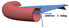
-
Select Accelerated and specify a
Distance.
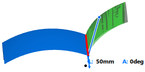
The flange edge opposite to the guide curve is moved in edge normal direction by the specified Distance.

You can specify a continuity from G1 to G3 in cross direction to the guide curve.
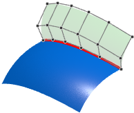
G1
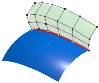
G2

G3
Note: This option is available for the flange surface type Surface Curve only.
