Adding and Removing Segments on Curves | ||||
| ||||
-
To start segment modeling, do one of the following:
- In the work area, press Alt + middle-click on a curve and select Modify Curve Segment
 in the mouse menu.
In the Segments Modeling panel, click
 to switch to subobject mode
  .
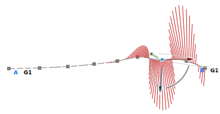
.Tip: If desired, click Analysis  to hide the curvature diagnosis.
 - In the Sculpt panel, click Activate Controls
 and Segments
 and clear Control Points
 .
.Right-click a curve to open the Segment Modeling panel. Subobject selection mode
 is automatically selected.
- In the work area, press Alt + middle-click on a curve and select Modify Curve Segment
-
Click Insert/Delete
 .
.
-
To insert segment boundaries, do one of the following:
- Move the pointer on the curve and press Insert.
- Click positions on the curve.
Segment boundaries are inserted at the selected positions.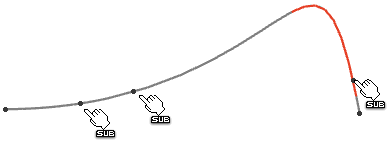
-
To delete segment boundaries, do one of the following:
- Move the pointer on the curve and press Delete.
- Click the segment boundaries on the curve.
-
Clear Insert/Delete
 and click Trim
 .
Note: This trim option creates a datum element and not an OmniCut feature.
.
Note: This trim option creates a datum element and not an OmniCut feature.- Trim the curve at a segment boundary keeping one side.
- Move the pointer to a segment. The curve region kept after the trim operation is highlighted.
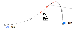
The pick position nearest to the next segment boundary determines the side to be kept.
- Click the segment to trim the curve.
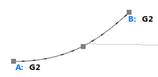
- Move the pointer to a segment. The curve region kept after the trim operation is highlighted.
- Trim the curve at a segment boundary keeping both sides.
- Move the pointer to a segment boundary. The whole curve is highlighted. To distinguish left and right side of the limitation, different highlight properties are applied.
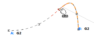
- Click the segment boundary to trim the curve.

- Move the pointer to a segment boundary. The whole curve is highlighted. To distinguish left and right side of the limitation, different highlight properties are applied.
Tip: Press Ctrl and select multiple segment boundaries. The curve is trimmed at the selected segment boundaries when releasing the Ctrl key. Instead of the segment boundaries, the trimmed curve boundaries are now displayed. Click a segment boundary again while keeping the Ctrl key pressed to deselect a segment boundary.
- Trim the curve at a segment boundary keeping one side.
-
Clear Trim
 and use the Segment Numbers box to insert segment boundaries.
If Segment Type Manual is selected, the segments are equally spaced along the curve.
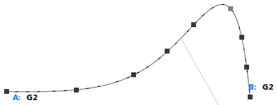
At the curve ends are displayed continuities.
- Click the continuity label at one of the curve ends to select the continuity to be kept at this side when modifying the inner segment boundaries.
-
In the Segment Modeling panel or the More section of the Sculpt panel, select Segment Type Arc Length.
Ratio determines the segment distribution:
-
Set the Ratio 0.0 (Arc Length).
The segments are equally spaced along the curve.

-
Set the Ratio 1 (Curvature).
The segments are distributed depending on the curvature degree.
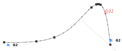
This may cause a deviation from the original curve which is displayed at the curve and in Deviation in the context menu.
- Move the pointer on the curve and press Alt + right-click.
-
In the mouse menu, select 1/3 Curvature.
The Ratio value in the Sculpt panel is set to 0.33.
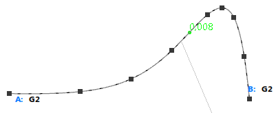
Tip: You can also select the segment type and ratio using the mouse menu with Alt + right-click on preselected segment. -
Set the Ratio 0.0 (Arc Length).
-
Click Order
 or
or  , respectively, to change the order accordingly.
-
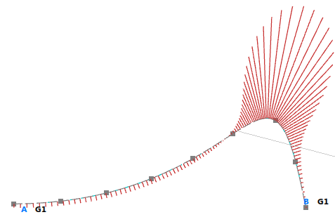
If deselected, click Analysis
 to display the curvature analysis.
-
Modify the view and then a segment.
The curvature analysis is displayed in the original direction.

-
Undo the segment modification and click Curvature Analysis Auto Direction
 .
.
-
Repeat the segment modification.
The curvature analysis is displayed according to the moved direction.
