General Principles
This topic provides the general principles you need when using the app.
Remote Control
- The entire screen reacts to selections and manipulations.
- Elements and handles can be remote-activated: the pointer does not need to be over an the element or very close to interact. The element that is closest to the pointer is selected. For elements such as faces or edges, the selection point is their barycenter. This gives you a real productivity gain and a very fast interaction with elements and handles.
-
Using a trap as a selection means is advised. Press Shift and drag to draw the trap. As a combination, you can press Ctrl to add or remove elements to the selection. Elements are selected if their barycenter is included in the trap.
-
To manipulate and deform a curve or a surface, it is advised to double-click the curve or surface rather than clicking.
Modification in the right-hand
toolbar to improve the productivity.
Escape Key
Use the Escape (Esc) key to exit a command.
Smart Selection
When selecting a feature and launching any command, all the parent features (subdivision surfaces or styling curves) are temporarily highlighted to enable an easy selection. The selected feature is also temporarily hidden.
Positioning of the created geometry
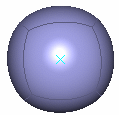
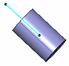
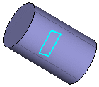
When an element (point, line, plane) is already selected before entering a command, it is used to define the position and orientation of the created primitive.
Thus,
- One point defines the barycenter.
- Two points define the main axis and the middle of the points define the barycenter.
- Three points define a plane and the normal to the plane defines the main axis.
- A line defines the main axis and its origin defines the barycenter.
- A plane's origin defines the barycenter and the normal to the plane defines the main axis.
Fast Manipulation
When modifying an object, you can manipulate the nearest element to the pointer without selecting it.
From the Tools Palette, you can select Manipulator
On/Off
![]() .
The robot's display becomes smaller and is placed on the nearest element to be
manipulated. It is no longer displayed on the barycenter of the selected elements, even in
case of multi-selection.
.
The robot's display becomes smaller and is placed on the nearest element to be
manipulated. It is no longer displayed on the barycenter of the selected elements, even in
case of multi-selection.
Handle Representation
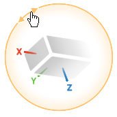
Here is the representation of the handle during a modification, for example while
performing a rotation: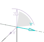

The semi-transparent zone represents the planes of the handle. It can be hidden by the subdivision surface if it is put behind.
Step by Step Modification
This capability is available with the Translation, Rotation, Local Normals and Mesh Lines commands.
To select the elements to be manipulated, press Ctrl and move the pointer to automatically compute the step. By default, the step corresponds to a power of 10 or 5° for the rotation.
| Tip: If you move the elements and then you press Ctrl, the step will be computed depending on the first displacement value. |
Robot
You can manipulate (move and rotate) the subdivision surfaces and styling curves using the Robot. These capabilities work exactly as in the basic interface command, therefore this section of the documentation actually links the 3DEXPERIENCE Native Apps User's Guide. Note that the information detailed in this section is presented in an Infrastructure environment different from the Imagine & Shape environment (symbols, background color, for example).
See:
- 3DEXPERIENCE Native Apps: V6 Signature : Using the Robot : Manipulate Objects Using the Mouse and Robot
- 3DEXPERIENCE Native Apps:V6 Signature : Using the Robot : Manipulate Objects Using the Edit... Command

