Constraint Options

The following constraints offer some orientation options.

This page discusses:

Coincidence

A Coincidence constraint offers the following option according to the selected elements.

Plane-Plane or Line-Line

When two planes, or two lines, are selected, one option is offered with three choices:

Option
Undefined: the orientation is undefined and can be modified during the PLM update.
Same: the orientation is the same.
Opposite: the orientation is opposite.

Contact

A Contact constraint offers the following option according to the selected elements.

Plane-Plane

When two planes are selected, one option is offered with three choices:

Option
Undefined: the orientation is undefined and can be modified during the PLM update.
Same: the orientation is the same.
Opposite: the orientation is opposite.

Hinge

A Hinge constraint between planes offers the following option.

When two planes are selected, one option is offered with four choices:

Option
Sector 1: the planes are oriented according to the first sector.
Sector 2: the planes are oriented according to the second sector.
Sector 3: the planes are oriented according to the third sector.
Sector 4: the planes are oriented according to the fourth sector.

Offset

An Offset constraint offers the following options according to the selected elements.

Plane-Plane

When two planes are selected, two options are offered with three choices each:

First Option
Undefined: the plane's position is undefined and can be modified during the PLM update.
Above: the second plane is positioned above the first plane.
Below: the second plane is positioned below the first plane.
Second Option
Undefined: the plane orientations are undefined and can be modified during the PLM update.
Same: the plane orientations are the same.
Opposite: the plane orientations are opposite.

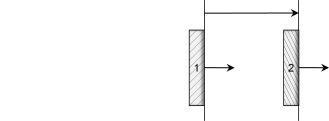
Tables above explain how instances are successively positioned according to the selected options.

Important:

Leaving the plane orientations undefined may allow an inversion of the components' repositioning during:

  • PLM update process,
  • or move under constraint,
  • or using Assembly Design Manipulation command.

Engineering Connection Orientation First Option Second Option Scheme
Position first instance Undefined Undefined
Position first instance Below Undefined
Position first instance Below Same
Position first instance Below Opposite
Position second instance Below Opposite
Position second instance Below Same
Position second instance Above Same

Line-Line

When two lines are selected, one option is offered with four choices:

Option
Undefined: the line orientations are undefined and can be modified during the PLM update.
Parallelism: the lines are parallel but not oriented.
Same: the orientations are the same.
Opposite: the line orientations are opposite.

Plane-Line or Plane-Point

When a plane and a line, or a plane and a point, are selected, one option is offered with three choices:

Option
Undefined: the orientation is undefined and can be modified during the PLM update.
Same: the orientation is the same.
Opposite: the orientation is opposite.

Roll Curve

A Roll Curve constraint between curves offers the following option.

Curve-Curve

When two curves are selected, one option is offered with three choices:

Option
Undefined: when the angle between the tangent vectors is lower than 90°, the Same behavior is considered during the PLM Update. When the angle between the tangent vectors is greater than 90°, the Opposite behavior is considered during the PLM Update.
Same: the constraint is satisfied when the angle between the tangent vectors is equal to 0°.*
Opposite: the constraint is satisfied when the angle between the tangent vectors is equal to 180°.*

*According to the precision of the current design range. For more information, see 3DEXPERIENCE Native Apps: Introducing Design Range Management.

Slide Curve

A Slide Curve constraint between curves offers the following option.

Curve-Curve

When two curves are selected, one option is offered with three choices:

Option
Undefined: when the angle between the tangent vectors is lower than 90°, the Same behavior is considered during the PLM Update. When the angle between the tangent vectors is greater than 90°, the Opposite behavior is considered during the PLM Update.
Same: the constraint is satisfied when the angle between the tangent vectors is equal to 0°.*
Opposite: the constraint is satisfied when the angle between the tangent vectors is equal to 180°.*

*According to the precision of the current design range. For more information, see 3DEXPERIENCE Native Apps: Introducing Design Range Management.

Symmetry

A Symmetry constraint between axes system offers the following option.

Axis System-Axis System

When two-axes systems are selected, one option is offered with three choices:

Option
Flip x: symmetry is oriented according to x axes.
Flip y: symmetry is oriented according to y axes.
Flip z: symmetry is oriented according to z axes.

Tangency

A Tangency constraint offers the following option according to the selected elements.

Plane-Surface

When a plane and a surface are selected, one option is offered with three choices:

Option
Undefined: when the angle between the plane and the surface normals is lower than 90°, the Same behavior is considered during the PLM Update. When the angle between the plane and the surface normals is greater than 90°, the Opposite behavior is considered during the PLM Update.
Same: the constraint is satisfied when the angle between the plane and the surface normals is equal to 0°.*
Opposite: the constraint is satisfied when the angle between the plane and the surface normals is equal to 180°.*

*According to the precision of the current design range. For more information, see 3DEXPERIENCE Native Apps: Introducing Design Range Management.