Constraint Symbols | |||||
|
| ||||
| Constraints | Symbols used in the work area | ||
|---|---|---|---|
| Angle |
 |
||
| Coincidence |
 / /
|
||
| Curvilinear |

|
||
| Contact |
 / /
|
||
| Fix |

|
||
| Fix Symmetry |
/

|
||
| Fix together |

|
||
| Hinge | Sector 1: angle |
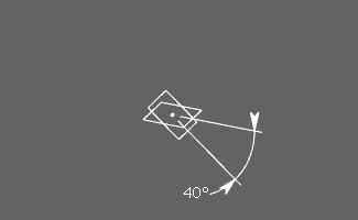 |
|
| Sector 2: 180 deg + angle |
 |
||
| Sector 3: 180 deg - angle |
 |
||
| Sector 4: 360 deg - angle |
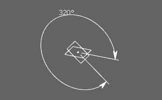 |
||
| Offset |
 |
||
| Parallelism |
 |
||
| Perpendicularity |
 |
||
| Roll |

|
||
| Symmetry |
|
||
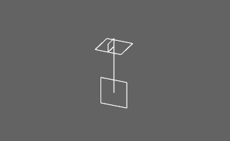
| Slide |

|
||
Important:
|