About Defining Constraints in a Mechanism | ||||||
|
| |||||
You can use specific constraints combinations to create common and predefined engineering connection types. To define another type of constraint combination, use a User-Defined engineering connection.
In the context of a product assembly, the restricted degrees of freedom determine the relative orientation between two parts. However, in the context of a mechanism, the unrestricted degrees of freedom determine how parts can move in the assembly.
You can define different types of constraints:
| Constraint Type | Description |
|---|---|
| driving constraint | An absolute constraint that defines fixed relative positions between two components in a product. |
| controlled constraint | A value-based constraint whose value can change. Mechanism commands are based
on controlled constraints. Note:
Controlled constraints are only available for
offset, curve, and angle constraints.
|
When defining controlled constraints, you must use specific geometry types as supports. Restricted geometry combinations can lead to ambiguous configurations in the mechanism. You cannot assign commands to these constraints in the Mechanism Manager (see Setting Up a Mechanism). The following table lists the allowed and restricted geometry combinations for controlled constraints in mechanisms.
| Controlled Constraint Type | Allowed Geometry Combinations | Restricted Geometry Combinations | ||
|---|---|---|---|---|
| Selection 1 | Selection 2 | Selection 1 | Selection 2 | |
| Offset | Plane or Face | Plane or Face | Point or Vertex | Point or Vertex |
| Plane or Face | Line or Edge | Point or Vertex | Line or Edge | |
| Plane or Face | Point or Vertex | Line or Edge | Line or Edge | |
| Angle | Plane or Face | Plane or Face | Line or Edge | Line or Edge |
| Plane or Face | Line or Edge | |||
Constraint Examples
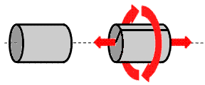
Consider a coincidence constraint applied to the axes of two cylinders. The two cylinders are constrained to rotate about the same axis, although their position on the axis is not constrained. This type of constraint corresponds to a cylindrical engineering connection. In the mechanism, the cylinders can rotate and slide along the axis.

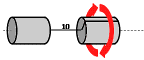
An additional offset constraint is defined to fix the distance between the two cylinders at 10mm. This combination of constraints corresponds to a revolute engineering connection. The cylinders can still rotate about the axis, but they can no longer slide freely along it.

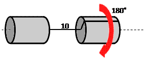
Finally, a controlled angle constraint is applied to the relative rotation between the cylinders. The cylinders are still free to rotate about the axis but only between 0 and 180 degrees.
