Adding an Axial Spring | |||
| |||
-
From the Mechanical Systems Design section of the action bar,
click
Axial Spring
 .
The Connection Property dialog box appears.
.
The Connection Property dialog box appears. -
Select the type of translational stiffness:
- Select Linear and enter the value of the force over displacement.
- Select Nonlinear and enter the values of the force over displacement in the table.
Note: If you select Nonlinear, enter the force and displacement values according to the selected force type.Force type Force/Moment (N) Displacement/Rotation (mm) Compression only Enter decreasing force values. Enter negative displacement values. Extension only Enter increasing force values. Enter positive displacement values. Bidirectional Enter decreasing and increasing force values. Enter positive and negative displacement values. Table 1. Examples of Generated Slopes for Each Force Type Compression only Extension only Bidirectional 
l F (lb) Dl (in) 1 -1.3 0 2 -3.3 -1.1 3 -9 -5.7 4 -16.4 -9.1 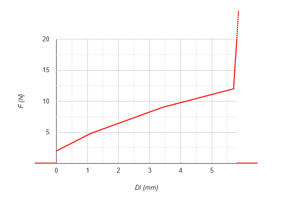
l F (lb) Dl (in) 1 2 0 2 4.8 1.1 3 12 5.7 4 10.000 5.8 
l F (lb) Dl (in) 1 -849 - 0.005 2 -376 - 0.0035 3 14 0 4 182 0.002 5 700 0.006 Important: The generated slope must always be positive to be physically valid. Notes:- For the slope to go through the origin, set both the Force value and the corresponding Displacement value to 0.
- To obtain the stopping point of an extension spring, enter a high-magnitude value in the last Force (F) cell.