About Traces | ||
| ||
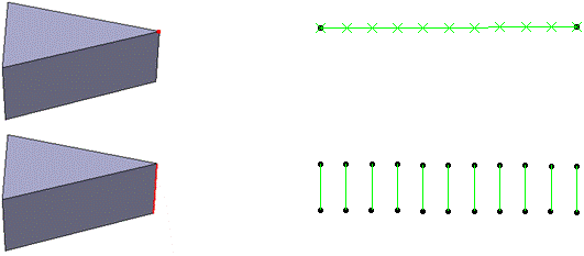
Traces can be performed on points, vertex, curves, and edges. A trace collectively plots the position of the selected element at each step in the simulation. For point traces, a line is also drawn to connect the resulting points in the trace.
The following figures illustrate a vertex trace (top), a straight edge
trace (middle), and a curved edge (bottom) on a simple part that
moves from left to right:

Traces are always performed relative to a reference product, which can change the shape of the generated geometry. The default is a stationary, universal reference axis sytem, so the generated geometry represents the true motion of the selected entities in three-dimensional space. However, it is possible to select another moving product in the mechanism as a reference product, in which case the trace represents relative motion as seen from the specified reference product.
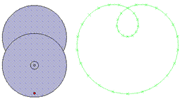
Consider a two-wheel mechanism: one wheel is fixed to the ground
and can rotate about its center; the other wheel is fixed to a
point on the rim of the first wheel, and it can also rotate about
its center. Over the course of a simulation, both wheels rotate a
full 360°; a trace is generated for a
point on the rim of the second wheel. Using the default universal
reference axis system, the trace captures both the translation and the
rotation of the second wheel:
However, there is no relative translational motion between the
first and second wheel. Therefore, if the first wheel is selected
as the reference product, the translational motion in the trace
disappears and only the rotation of the second wheel is
captured: