Selecting Reference Planes for a Building Grid: Example | |||
| |||
Context: This example, which has the Ground Story as the lowest level, uses the Reference Plane feature of the Building Grid. It shows how to take advantage of Story Elevation reference plane, located in the tree in the Reference Elements for each story.
-
Create a structural grid
sketch to use as the basis of the Building Grid.
-
From the
Building section of the
action bar,
click
Positioned Sketch
 .
Note: You can create a sketch using Sketcher.
 - In the 3D area, create a sketch.
-
In the
Sketcher
app, in the
Sketch section of the
action bar,
click
Exit App
 .
.
-
From the
Building section of the
action bar,
click
Positioned Sketch
-
From the
Building section of the action bar, click
Building Grid
 .
.
- In the 3D area or tree, select the sketch that you want to include in the building grid.
-
Add the reference plane information as follows:
- Click Reference Plane.
- In the tree, for each story, expand Reference Elements.
- Click Input Bodies to select input bodies.
-
To transform the grid:
-
Click
Grid Transformation Options
 .
.
- Click Select Spine.
-
From the
3D area,
select a spine.
By default, the system uses the global z axis as the spine. While transforming the grid, the system scales and twists about the points where the spine intersects with the output grid planes.
Important: The spine must intersect all output grid planes. -
In the
Reference Planes Grid dialog box, scale the
grid either by:
Option Description Using a law - Select the Use law for scale check box.
- From the tree, select a law.
The system uses the law as a reference to scale the grid.
Tip: Use a law to scale the grid nonlinearly. Manually - In Scale start, enter the scale of the grid at the bottom of the starting story.
- In
Scale end, enter the scale
of the top of the uppermost story of the grid.
Note: If you have entered a Roof Thickness value, the Scale end value determines the scale of the virtual roof.
-
In the
Reference Planes Grid dialog box, twist the
grid either by:
Option Description Using a law - Select the Use law for twist angle check box.
- From the tree, select a law.
The system uses the law to obtain twist angle values at each output grid plane.
Tip: Use a law to twist the grid nonlinearly. Manually - In Twist start angle, enter the angle of the grid at the starting story.
- In
Twist end angle, enter the
angle of the uppermost story of the grid.
Note: If you have entered a Roof Thickness value, the Twist end angle determines the angle of the virtual roof.
-
Click
Grid Transformation Options
-
Click
 .
.
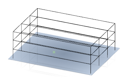
The resulting building grid covers all the stories even though the
building includes only a single primary slab at the bottom of the grid.
