Create Regions and Bands
You
can create curtain wall regions and bands within a variable curtain wall using reference
planes and reference points.
-
From the Building section of the action bar, click Variable Curtain
Wall
 . .
-
In the 3D area, select the face where you want to
create a curtain wall.
You can select multiple faces only if the faces are tangent continuous to
each other.
-
To create horizontal bands:
-
In the Variable Curtain Wall dialog box,
click Horizontal Bands
 . .
-
In the 3D area or from the tree, select reference planes to
position the horizontal bands.
The system places horizontal bands where the reference plane meets
the selected face.
-
To create vertical bands:
-
In the
Variable Curtain Wall dialog box, click
Vertical Bands
 . .
-
In the
3D area
or from the
tree,
select reference points to position the horizontal bands.
The system places vertical bands where the reference points are
projected to the baseline of the variable curtain wall.
The system creates regions and bands. Regions in the variable curtain
wall are demarcated by the horizontal and vertical bands.
Edit Regions and Bands
You
can create unique mullion patterns in bands and regions. You can also share mullion
pattern definitions between regions or between bands.
-
In the
Variable Curtain Wall dialog box, click
Area Pattern
 to activate the selected faces for editing. to activate the selected faces for editing.
Alternatively, select a band or region in the
3D area.
-
To edit vertical mullions in a region or a horizontal band:
-
In the Variable Curtain Wall dialog box, click
Vertical Mullion Pattern
 . .
-
To create a repeating pattern of vertical mullions using the
horizontal spacing between mullions:
- Click Horizontal Spacing
 . .
- Select one of the following anchor lines for the mullion
pattern:
- Center
 : The system displays the
anchor with a vertical blue line at the center of
the selected faces. : The system displays the
anchor with a vertical blue line at the center of
the selected faces. Note:
To mirror the pattern
about the center anchor line, click Mirror  . .
- Left
 : The system displays the
anchor with a vertical blue line at the left of the
selected faces. : The system displays the
anchor with a vertical blue line at the left of the
selected faces.
- Right
 : The system displays the
anchor with a vertical blue line at the right of the
selected faces. : The system displays the
anchor with a vertical blue line at the right of the
selected faces.
- Select one of the following panel size refinements to be
made at the boundary of the selected area:
- None
 : Maintain the panel width at
the boundary of the curtain wall area. : Maintain the panel width at
the boundary of the curtain wall area.
- Shrink
 : Decreases the panel width at
the boundary to avoid creating panels less than half
of the narrowest specified panel width. : Decreases the panel width at
the boundary to avoid creating panels less than half
of the narrowest specified panel width.
- Grow
 : Increases the panel width at
the boundary to avoid creating panels less than half
of the narrowest specified panel width. : Increases the panel width at
the boundary to avoid creating panels less than half
of the narrowest specified panel width.
- To create a horizontal running bond pattern, in the 3D area, select a region or a
horizontal band. Then, in the Variable Curtain
Wall dialog box, under Vertical
Mullion Pattern, in Row
Offset, enter a value.
The system creates
a running bond pattern by applying the row offset value
to alternating rows.
-
To create a number of equal horizontal panels, click
Horizontal Count
 . In the
3D area,
enter the required number of panels in the value box. . In the
3D area,
enter the required number of panels in the value box.
-
To create equally sized panels with a horizontal size as
close as possible to an optimal value, click
Optimal Width
 . In the
3D area,
enter the optimal horizontal size in the value box. . In the
3D area,
enter the optimal horizontal size in the value box.
-
To create equally sized panels with a horizontal size that
are as large as possible, but not larger than a maximum value, click
Maximum Width
 . In the
3D area,
enter the maximum horizontal size in the value box. . In the
3D area,
enter the maximum horizontal size in the value box.
-
To edit horizontal mullions in a region or a vertical band:
-
In the
Variable Curtain Wall dialog box, click
Horizontal Mullion Pattern
 . .
-
To create a repeating pattern of horizontal mullions using the
vertical spacing between mullions:
- Click Vertical Spacing
 . .
- Select one of the following anchor lines for the mullion
pattern:
- Middle
 : The system displays the
anchor with a horizontal blue line at the middle of
the selected faces. : The system displays the
anchor with a horizontal blue line at the middle of
the selected faces. Note:
To mirror the pattern
about the center anchor line, click Mirror  . .
- Top
 : The system displays the
anchor with a horizontal blue line at the top of the
selected faces. : The system displays the
anchor with a horizontal blue line at the top of the
selected faces.
- Bottom
 : The system displays the
anchor with a horizontal blue line at the bottom of
the selected faces. : The system displays the
anchor with a horizontal blue line at the bottom of
the selected faces.
- Select one of the following panel size refinements to be
made at the boundary of the selected area:
- None
 : Maintain the panel width at
the boundary of the curtain wall area. : Maintain the panel width at
the boundary of the curtain wall area.
- Shrink
 : Decreases the panel width at
the boundary to avoid creating panels less than half
of the narrowest specified panel width. : Decreases the panel width at
the boundary to avoid creating panels less than half
of the narrowest specified panel width.
- Grow
 : Increases the panel width at
the boundary to avoid creating panels less than half
of the narrowest specified panel width. : Increases the panel width at
the boundary to avoid creating panels less than half
of the narrowest specified panel width.
- To create a vertical running bond pattern, in the 3D area, select a vertical
band. Then, in the Variable Curtain
Wall dialog box, under Horizontal
Mullion Pattern, in Column
Offset, enter a value.
The system creates
a running bond pattern by applying the column offset
value to alternating columns.
-
To create a number of panels of equal vertical size, click
Vertical Count
 . In the
3D area,
enter the required number of panels in the value box. . In the
3D area,
enter the required number of panels in the value box.
-
To create equally sized panels with a vertical size as close
as possible to an optimal value, click
Optimal Width
 . In the
3D area,
enter the optimal vertical size in the value box. . In the
3D area,
enter the optimal vertical size in the value box.
-
To create equally sized panels with a vertical size that are
as large as possible, but not larger than a maximum value, click
Maximum Width
 . In the
3D area,
enter the maximum vertical size in the value box. . In the
3D area,
enter the maximum vertical size in the value box.
-
To edit patterns in a band or region:
-
In the 3D area, select a band or region.
-
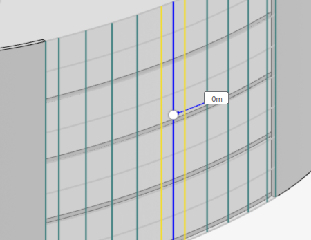
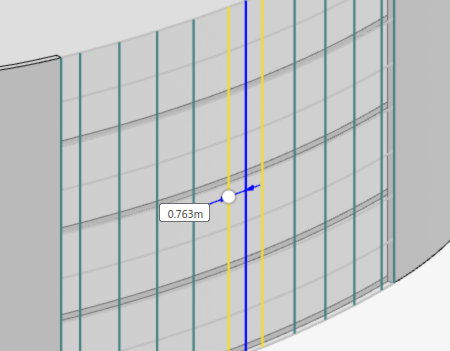
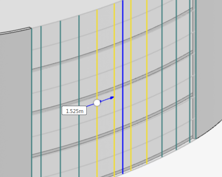
To change the position of the band, drag the handle on the blue
line.

-
To change the height or width of the panel in a band, drag the
handle on the yellow line.

-
To include more mullions in the pattern, click a green line. The
system turns the selected green line into a yellow line. You can
then drag the handle on the new yellow line to edit the height or
width of the current set of panels.

-
To copy dimensions, patterns, or display properties from a
region or band:
-
In the
Variable Curtain Wall dialog box, click
Match
 . .
-
In the
3D area,
select the region or band from where you want to copy a pattern or property.
Note:
You can select regions or bands of the same type. For example,
two horizontal bands can match their display patterns, but a
horizontal band cannot match their pattern with a vertical band.
Match, Make Unique, or Make Similar
You can replicate or share pattern definition between multiple
regions. Horizontal bands can share pattern definition with other horizontal bands.
Vertical bands can share pattern definition with other vertical bands.
Context:
By default, all regions in a single variable curtain wall share the same pattern.
-
To create a unique pattern definition in a region or band:
-
From the
3D area,
right-click the region or band.
-
Click
Make Unique.
The selected region or band hosts a unique pattern definition.
-
To share a pattern definition across multiple regions or bands:
-
Activate the source region or band.
-
From the
3D area,
right-click the region or band that receives the pattern.
-
Click
Make Similar.
Note:
Make Similar appears only when the
region or band contains a different pattern definition.
Regions or bands of the same type share the selected pattern
definition.
-
To copy a pattern definition from one region to another:
-
Activate the target region or band.
-
In the
Variable Curtain Wall dialog box, click
Match
 . .
-
In the
3D area,
select the region or band from where you want to copy a pattern or property.
Note:
You can match pattern definition from a region or band in a
different variable curtain wall.
The system copies the pattern definition of the active region to
the pattern definition of the selected region. The system also copies
display properties of the active region to the display properties of the
selected region.
-
To copy an entire variable curtain wall to a new host surface:
-
From the
Building section of the
action bar,
click
Variable Curtain Wall
 . .
-
In the
3D area,
select the new host surface.
-
In the
Variable Curtain Wall dialog box, click
Match
 . .
-
In the
tree,
select the variable curtain wall.
-
Click
 . .
The system copies the horizontal bands and regions of the
variable curtain wall to the new host surface. Vertical bands are not
copied.
-
To copy a variable curtain wall to the same host surface:
-
From the
Building section of the
action bar,
click
Variable Curtain Wall
 . .
-
In the
Variable Curtain Wall dialog box, click
Match
 . .
-
In the
tree,
select the variable curtain wall.
-
In the
Variable Curtain Wall dialog box, click
Curtain Options
 . .
-
In
Surface Offset, enter the curtain wall
offset.
Curtain wall offset is measured perpendicular to the
panels, away from the building mass. Negative values flip the direction of the
offset.
-
Click
 . .
Note:
You can create variable curtain walls on the same host surface to
create multilayer curtain walls or rain screens.
The system copies the variable curtain wall to the same host
surface.
Set Curtain Options
You can set properties that affect the entire curtain wall.
-
In the
Variable Curtain Wall dialog box, click
Curtain Options
 . .
The system displays curtain wall options.
-
To set vertical mullions to follow isoparametric lines on the
surface instead of lines formed by vertical plane cuts, click the
Isoparametric vertical mullions check box.
-
To orient the horizontal mullions parallel to the xy plane
instead of normal to the surface, click the
Horizontal mullions parallel to ground check
box.
-
To merge triangular cells formed by vertical lines intersecting
a side of the curtain wall, click the
Merge triangular cells check box.
-
To join mullions, click the
Join Mullions check box.
The system performs a Boolean join operation on mullions. For
better system performance, clear the Join Mullions
check box.
-
To create mullions on the edges produced by cutouts, click the
Mullions at cutouts check box. The system
creates mullions at the edges of doors, windows, openings, glazed panel walls,
and other cutouts.
-
To flip the side of the input faces on which the system creates
the curtain wall, click the
Opposite side check box.
-
In
Surface Offset, enter the curtain wall
offset.
Curtain wall offset is measured perpendicular to the panels, away from
the building mass. Negative values flip the direction of the offset.
Set Area Properties
You can edit the dimensions of mullions and panels in the variable
curtain wall.
Context:
In the Variable Curtain Wall dialog box, click
Area Properties
 . .
-
Select the Horizontal mullions check box to create
horizontal mullions.
-
In the Width box, enter the width of
horizontal mullions. Mullion width is measured parallel to the
surface of the panel.
-
In the Depth box, enter the depth of
horizontal mullions. Mullion depth is measured perpendicular to the
panel, toward the building mass.
-
In the Offset box, enter the offset of the
horizontal mullions. Mullion offset is measured perpendicular to the
panel, away from the building mass. Negative values flip the
direction of the offset.
-
Select the Vertical mullions check box to create
vertical mullions.
-
In the Width box, enter the width of
vertical mullions. Mullion width is measured parallel to the surface
of the panel.
-
In the Depth box, enter the depth of
vertical mullions. Mullion depth is measured perpendicular to the
panel, toward the building mass.
-
In the Offset box, enter the offset of the
vertical mullions. Mullion offset is measured perpendicular to the
panel, away from the building mass. Negative values flip the
direction of the offset.
-
Select the Ascending diagonal mullions check box to
create ascending diagonal mullions and select the Descending
diagonal mullions check box to create descending diagonal
mullions.
-
In the Width box, enter the width of the
diagonal mullions. The mullion width is measured parallel to the
surface of the panel.
-
In the Depth box, enter the depth of the
diagonal mullions. The mullion depth is measured perpendicular to
the panel, toward the building mass.
-
In the Offset box, enter the offset of the
diagonal mullions. The mullion offset is measured perpendicular to
the panel away from the building mass. Negative values flip the
direction of the offset.
-
Under
Panel:
-
In
Thickness, enter the thickness of
panels. Panel thickness is measured perpendicular to the building face, toward
the building mass.
-
In
Offset, enter the offset of the panels.
Panel offset is measured perpendicular to the building face, away from the
building mass. Negative values flip the direction of the offset.
-
Under
Border Mullions, in
Between regions, select the width of the
border mullions between regions.
Note:
The system generates the width of vertical and horizontal border
mullions using the width of other vertical and horizontal mullions
respectively.
- Half: The system creates border mullions that
are half the width of other mullions.
- Full: The system creates border mullions that
are the same width as the other mullions.
- None: The system does not generate border
mullions.
-
Under
Graphic:
-
Click
Panel color to select a color from the
Color Picker dialog box. You can use the
Color Wheel,
Square with Hue, or Hexadecimal color
codes to set the color.
-
To set panel transparency, under
Panel color, drag the
Transparency slider.
-
Click
Mullion color to select a color from the
Color Picker dialog box.
-
To set mullion transparency, under
Mullion color, drag the
Transparency slider.
|


