Creating Measures

You can measure different parameters of an object such as area and the distance between two objects.

You can also measure along a direction, where you can specify the direction along which you want to measure.

This task shows you how to:

Measure Items

You can measure the different parameters of an object such as the area, the center of gravity or the perimeter.

  1. From the Review section of the action bar, click Measure.
    The Measure panel appears.
  2. In the Measure panel, select the required measure specifications such as measure type, measure mode etc. For more information, see About Refining Criteria.
  3. Select the item you want to measure.

    Note: You can select the required type of measure from the context toolbar also.
    Tip: You can Ctrl+ select the multiple objects of the same type. The displayed measure is the sum of the measures of the individual objects. You can click , available next to the respective selection boxes to manage your selections.

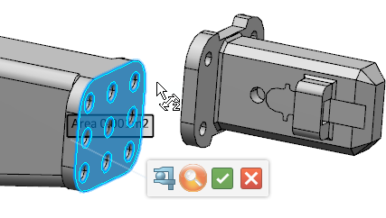
    The measure value for the selected item, a context toolbar, and the Measure Customization panel are displayed.

    You can show or hide various measure parameters in the Measure Customization panel or on the context toolbar. For more information about the various measure customization options, see Measure Context Toolbars.

  4. In the Customize tab, select the parameters to be displayed in the 3D area and under the results.

    Note: In the tree, the KWE parameters are displayed for only the measured parameters selected in the Tab list.

  5. On the context toolbar, click Validate the Measure .
    The measure is created. By default, the measure is in the active state.
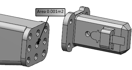
    Note: In case of center of gravity, the geometrical center of gravity of the object is calculated without taking into account the applied material.
  6. Select the created measure and click Add Comment on Measure on the context toolbar.
  7. Enter the required comment in the box, select the appropriate font style and size, and click .
    The comment is added to the measure.
  8. Optional: To change the font style and size of the measure text,
    1. Select the measure.
    2. On the context toolbar, click Change font size and style of measure text.
    3. Select the desired font style and size, and click .
    The font style and size of the measure text excluding the comment are changed.
Measure Between Items

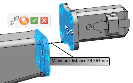
You can measure the distance between the items.

  1. From the Review section, click Measure .
    The Measure panel appears.
  2. In the Measure panel, select the required measure specifications such as the measure type, the measure mode etc. For more information, see About Refining Criteria.

    Note: For polyhedral data, the distance between two points can be measured only for the points selected using the Picking Point mode.

  3. Select the first item in the geometry.

    Note: You can select the required type of measure such as Minimum distance from the context toolbar also.

    The selected item is highlighted and the pointer changes to the second selection pointer . For more information, see About Measure Pointers.

  4. Select the second item in either the geometry or, if applicable, the tree.
    The second item is highlighted and the measure value is displayed.


    Tip: You can Ctrl+ select multiple items to create a group selection. The objects in the Selection 1 are considered as the first group, and the objects in the Selection 2 are considered as the second group. The minimum distance is computed as the shortest distance between the two groups.
  5. On the context toolbar, click Validate the Measure .
    The measure is created.
  6. In the Customize tab, select the parameters to be displayed in the 3D area and under the results.

    Note: In the tree, the KWE parameters are displayed for only the measured parameters selected in the Tab list.

Tips:
  • You can move the measure text box and position it as required.
  • You can drag the dimension line in the desired direction. Extension lines appear from the point of measure to the dimension line.
  • You can move the text box and align the measure leader to the dimension line. You can align it either perpendicular to or along the dimension line.
  • When you measure an angle, you can drag the arc in the opposite direction to compute its conjugate.
Important:
  • The maximum distance from an entity to itself will be a finite distance between two extremities of the entity, except for geometries point and arc or circle with Any geometry selection mode.
  • When you select the object from the 3D area, the selected object is used for measure computation.
  • When you select the object from the 3D area, the selected object is used for measure computation.
  • When an object is unloaded, the associative measures linked to the object are not displayed in the 3D area. However, they are displayed in the tree with a dedicated mask.
  • You can measure the canonic polyhedral surface geometries such as plane, cylinder, cone, and sphere.
  • Measure result is computed approximately using picking point selection mode for "picking point" selection mode in apps like Assembly Design, Part Design, Design Review, and Design Synthesis.

Create Measure Recurrently

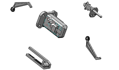
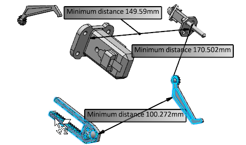
You can create the measures repeatedly by selecting the items one after another.

  1. From the Review section, click Measure .
    The Measure panel appears.
  2. In the Measure panel,
    1. From the list, select Minimum distance as a measure type.
    2. Click Chain Measure.
    3. Select the Keep only Last Measure check box to display the last measure in the work area.

      Notes:
      • This check box is available only for multiple measures and when the measure is non-persistent.
      • By default, this check box is cleared.

  3. Select the first item in 3D area.


  4. Select the second item.
  5. Keep on selecting the items one after the other.
    The measures values are displayed.

  6. On the context toolbar, click Validate the Measure .
    The measure is created.
  7. To create a positional link:
    1. Right-click the measure, and select Positional link > Create.
    2. Select an object from the tree.
  8. To replace or delete the positional link:
    1. Right-click the measure, and select Positional link > Replace.
    2. Select another object from the tree to create a new positional link.
    3. Right-click the measure, and select Positional link > Delete.

    Note: A positional link allows to ensure that the position of the measure text box follows the position of the associated object.