-
In the 2D Layout for 3D Design
tab, from the Compass, click Drafting.
The Drawing dialog box appears, allowing you to
enter information related to your new drawing representation. The
Drawing section lets you define general
attributes. For more information, see Creating New Content.
Don't forget to fill in the Title box. By default, a
name DrawingX (where X is a number) is specified.
- Select appropriate range in the Design Range list.
In this case, if the ranges of the drawing and that of the product are not compatible, a warning message of Scale compatibility problem appears in the 3D View Extraction dialog box. - Select the Drawing Information section.
In this case, if the ranges of the drawing and that of the product are not compatible, a warning message of Scale compatibility problem appears in the 3D View Extraction dialog box. For example, if the product or 3D area part is of large range, and the drawing preference is set at normal range, (or vice versa), then the message Scale compatibility problem appears. The following two scenarios are possible based on whether you have set attributes at creation: - If you have not set attributes at creation, use the following steps:
- Click OK in the 3D View Extraction dialog box.
The drawing range is automatically adapted to the range of the product or 3D area part (regardless of the range
stored as a preference in
expander, under Design Range) and
the drawing is created. - Click Cancel.
It uses the default range and therefore the Entry creation failed message appears. When you click Close, the message dialog box closes without generating the drawing.
- If you have set attributes at creation, use the following steps:
- Click OK in the 3D View Extraction dialog box.
The Drawing dialog box appears displaying the drawing preference range in the Design Range list. You can change the range to adapt to the product or 3D area range. - Click OK in the Drawing dialog box.
The drawing is generated matching with the product or 3D area part range.
- Optional: Click Cancel in the 3D View Extraction dialog box.
The Drawing dialog box appears displaying the drawing preference range in the Design Range list. In this case, the Drawing Information section displays the message Current range does not allow view generation. - In the Drawing section, change the drawing range to make it compatible with the product/3D area in the Design Range list.
- Click OK in the Drawing dialog box.
An empty drawing is generated matching with the product or 3D area part range.
Note:
When creating a drawing from a layout, the Insert drawing
in XXX option cannot be selected (where XXX is the name of the product).
- Select a standard, a sheet style and an orientation.
The sheet style defines among other things the sheet format, paper size
and scale.
- Select All
Design Sheets if not selected already (default selection).
If you select Empty sheet, an empty sheet is created. If several sheets are generated on the same 2D layout in the current session, the last sheet range option is saved as a preference to initialize the list for the next usage. Note:
If the drawing range and the range of the product/3D area part does not match, a message Current range does not allow view generation is displayed in this area.
- Click OK.
When the drawing is created,
the Drafting app is activated.
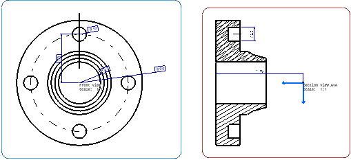
The created drawing is displayed with the same views as in the layout.
Notice that elements which are white in the layout are converted to
black in the drawing.

The created views are listed in the tree.
|