Creating Text | |||
| |||
-
From the Sketch section of the action bar, click Text
 .
.
The Text Creation dialog box appears.
Tools Palette displays boxes for defining the horizontal (H) and vertical (V) point coordinates to set the position of the text.
-
Locate the text align point:
- Click anywhere in the work area.
- If you know where this point must be located, enter the H and V coordinates in Tools Palette.
Important: You can select the linear, circular, or non canonical curve as a support to create the text. By default, the text is created along the horizontal direction, if the valid support curve is not defined. -
In the Text box, enter your text.
A preview of the text appears in the 3D area. This preview is updated each time you modify the values specified in the dialog box.
- Under Font, in the Font Type list, select the font to apply on the text.
- In the Font Size box, enter the value to define the height of the characters in the text.
- In the Font Style list, select the font style to apply on the text.
-
Under
Alignment, select one of the following options
to define the horizontal alignment of the text:
- Left Alignment

- Center Alignment

- Right Alignment

Note: These horizontal alignment options are dependent on the selection point on the curve. - Left Alignment
-
Select one of the following options to define the vertical
alignment of the text:
-
Descender

-
Baseline

-
Middle

-
Ascender

- Vertical

- Vertical left

- Vertical right

Note: These vertical alignment options are dependent on the support curve. -
Descender
-
Keep the default orientation of the text.
Note: You can click Indirect
 to change the orientation of the text with respect to the
support geometry.

- Under Spacing, in the Spacing box, enter the percentage value to add or reduce the spacing between each character of the text.
- In the Ratio box, enter the percentage value to define the ratio of the width of the characters in the text with respect to the height of the characters.
-
In the Anchor & Support box, specify the anchor
point and define a support curve for the text.
Notes:
- You can use Smartpick to position the text anywhere in the 3D area or you can snap it on a point or on a curve.
- When you right-click the Anchor & Support box, a context menu appears. You can center tree or reframe on the input point or input curve.
- If the anchor point is coincident with a curve, you can select Search support from anchor from the context menu to retrieve the curve from the anchor point.
-
Click
OK.
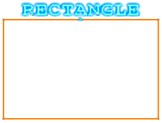
The text is created on the support curve.

Notes:- The Group
 constraint is created between a text and a support, if the
Create Detected
Constraints
 option is selected.
 - You can edit and modify the data of the sketch text such as text string, font, font size, alignment, spacing.
- The text is updated if the anchor point or the support curve is changed.
- The text data can also be driven by parameters and formula defined outside of sketch. The text string, font, and size can be managed by knowledge relations. If any one of these parameters is modified, the text is updated according to the knowledge relations.
- You cannot put constraints on a Text, add it into a Fix Together group, drag it, or move it with the help of any transformation command. You cannot perform any topological modification on a text, like break, trim, or corner operations. You cannot create any kind of output feature from a text.
- Only true type fonts and open type fonts are currently supported by the Text command.
Warning: : All 3D elements resulting from an associative text of sketch have the same naming. Thus, it is not possible to select a vertex, and edge or a face from this 3D result independently. - The Group