Composites Design Parameters | ||
| ||
Ply
| Parameters | Value | Description |
|---|---|---|
| Contour | yes/no | Determines whether the 3D contours of the plies should be extracted or not. |
| Exploded Surface | yes/no | Determines whether the exploded surfaces of the plies should be extracted or not. |
| Flatten | yes/no | Determines whether the flatten shapes of the plies should be extracted or not. |
| Highlight shell | yes/no | Determines whether a shaded ply/cut-piece should be generated in the drawing document, without generating the exploded surface in 3D part. The highlight shell inherit its color from the parent ply/cut-piece contour. |
| Seed point | yes/no |
Determines whether the seed points of the plies should
be extracted or not.
Note:
Only available if producibility parameters have been computed on
this feature.
|
| Seed curve | yes/no |
Determines whether the seed curves of the plies should
be extracted or not.
Note:
Only available if producibility parameters have been computed on
this feature.
|
| Rosette | yes/no | Determines whether the rosettes of the plies should be extracted or not. |
| Rosette Representation |
| Determines how the rosette is represented (Rosette must be set to yes). |
| Name | yes/no | Determines whether the names of the plies/cut-pieces should be extracted or not. |
| Contour thickness | 1-8 | Determines the thickness of contours. Note:
With 0 value, the 2D line inherits its thickness from the 3D
contour property.
|
| Other geometry | yes/no | Determines whether the geometry aggregated under the plies should be extracted or not. |
| Overwrite color inheritance | yes/no |
Forces the color of the plies even if is set to no. Note:
In the drawing view, ply contour lines may be hidden by 2D
representation of surfacic and solid elements.
To avoid this, set Project 3D wireframe to Is
always visible.
|
The name of ply/cut-piece is generated at anchor point, defined as:
- Either the seed point location if producibility parameters are defined.
- Or the projection of the contour center of gravity if located inside the ply contour.
- Or at the closest point on contour of this center of gravity.
Rosette transfer is computed at the ply/cut-piece anchor point and 0deg/90deg direction axis lines and X fiber direction axis line are displayed.
Symbolic texts indicate the 0deg/90deg axis in 2D view; X fiber direction axis line inherits color from the ply/cut-piece contour. Symbolic texts size for rosette axis and ply name respect the input scale factor. In , when you modify the scale of a previously generated view containing symbolic texts, not all texts sizes take into account this factor scale. To synchronize texts sizes with the view scaling, select the Apply Scale check box in Text tab of the properties of the selected annotations.
Core
| Parameters | Value | Description |
|---|---|---|
| Solid | yes/no | Determines whether the solid should be extracted or not. |
| Name | yes/no | Determines whether the name should be extracted or not. |
| Rosette | yes/no | Determines whether the rosette should be extracted or not. |
| Other geometry | yes/no | Determines whether the geometry aggregated under the core should be extracted or not. |
| Overwrite color inheritance | yes/no |
Forces the color of the core even if is set to no. Note:
In the drawing view, ply contour lines may be hidden by 2D
representation of surfacic and solid elements.
To avoid this, set Project 3D wireframe to Is
always visible.
|
Rosette transfer is computed at the projection of the solid center of gravity on the specified support surface and 0deg/90deg direction axis lines and X fiber direction axis line are displayed.
Symbolic texts indicate the 0deg/90deg axis in 2D view; X fiber direction axis line inherits color from the core solid. Composites Design does not display the rosette axis if the core feature has no parent ply group (no support surface to project on).
Symbolic texts size for the rosette axis and the core name respect the input scale factor (only available with the Advanced Front View command). In , when you modify the scale of a previously generated view containing symbolic texts, not all texts sizes take into account this factor scale. To synchronize texts sizes with the view scaling, select the Apply Scale check box in Text tab of the properties of the selected annotations.
Core Sample
| Parameters | Value | Description |
|---|---|---|
| 3D Label | yes/no | Determines whether the annotation at the CS point with the same text as the 3D label should be generated or not. |
| Table | yes/no | Determines whether a table with the list of plies at the CS point should be generated or not. |
| Table Column Plies Group Name | yes/no | Determines whether there should be a Plies Group column in the CS results table or not (Table must be set to yes). |
| Table Column Sequence Name | yes/no | Determines whether there should be a Sequence column in the CS results table or not (Table must be set to yes). |
| Table Column Entity Name | yes/no | Determines whether there should be an Entity Name column in the CS results table or not (Table must be set to yes). |
| Table Column Material ID | yes/no | Determines whether there should be a Material ID column in the CS results table or not (Table must be set to yes). |
| Table Column Material Name | yes/no | Determines whether there should be a Material Name column in the CS results table or not (Table must be set to yes). |
| Table Column Orientation Name | yes/no | Determines whether there should be an Orientation Name column in the CS results table or not (Table must be set to yes). |
| Table Column Orientation Value | yes/no | Determines whether there should be an Orientation Value column in the CS results table or not (Table must be set to yes). |
| Table Column Rosette | yes/no | Determines whether there should be a Rosette column in the CS results table or not (Table must be set to yes). |
Stacking
| Parameters | Value | Description |
|---|---|---|
| Generative Context | Table/3DView | When set to Table, only the Stacking Table is visible. Other geometry projections are omitted, provided you select only Stacking, and a plane to generate the drawing. |
| Table | yes/no | Determines whether there should be a table with stacking information. |
| Stacking Entity Level | Plies Group/Sequence/Ply/Cut Piece | Selects the entity level to display, as in Stacking Management |
| Column Plies Group | yes/no | Determines whether there should be a Plies Group column in the stacking table or not (Table must be set to yes). |
| Column Sequence | yes/no | Determines whether there should be a Sequence column in the stacking table or not (Table must be set to yes). |
| Column Ply | yes/no | Determines whether there should be a Ply column in the stacking table or not (Table must be set to yes). |
| Column Cut Piece | yes/no | Determines whether there should be a Cut Piece column in the stacking table or not (Table must be set to yes). |
| Column Material ID | yes/no | Determines whether there should be a Material ID column in the stacking table or not (Table must be set to yes). |
| Column Material Name | yes/no | Determines whether there should be a Material Name column in the stacking table or not (Table must be set to yes). |
| Column Orientation Name | yes/no | Determines whether there should be an Orientation Name column in the stacking table or not (Table must be set to yes). |
| Column Orientation Value | yes/no | Determines whether there should be an Orientation Value column in the stacking table or not (Table must be set to yes). |
| Column Rosette | yes/no | Determines whether there should be a Rosette column in the stacking table or not (Table must be set to yes). |
| Column Surface | yes/no | Determines whether there should be a Surface column in the stacking table or not (Table must be set to yes). |
| Column Draping | yes/no | Determines whether there should be a Draping column in the stacking table or not (Table must be set to yes). |
| Column Core Sample | yes/no | Determines whether there should be a Core Sample column in the stacking table or not (Table must be set to yes). |
Examples:
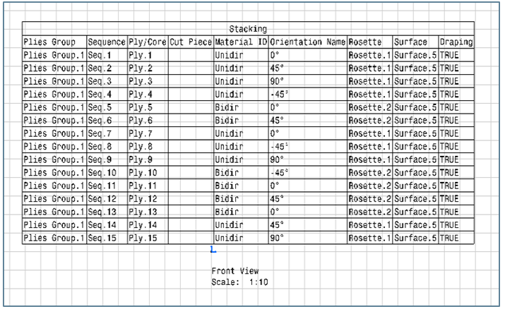
- Generative Context is set to Table. Stacking and plane have been selected to create the drawing. The image shows only the Stacking Table.

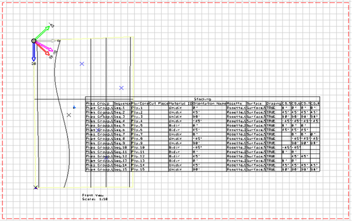
- Generative Context is set to Table. Only the projection plane has been selected to create the drawing. The image shows the Stacking Table along with default projections of non-composite geometries. Composite geometry projections (Ply/Core) are omitted.

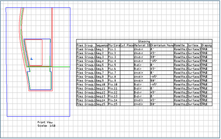
- Generative Context is set to 3DView. Stacking and plane have been selected to create the drawing. The image shows the Stacking Table as well as Ply, Core.' projections. Non-composite geometries are omitted as Stacking has been selected, but composite geometries are taken into account.

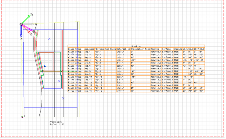
- Generative Context is set to 3DView. Only the projection plane has been selected to create the drawing. The image shows the Stacking Table and all other possible geometric projections (composites/non-composites).
