Create a 3D profile on the view support plane
You can create a 3D profile on the view support plane.
- Double-click to activate the design view you will be working in.
-
From the customized section of the action bar, click 3D Profile
 .
.
-
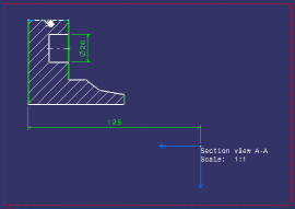
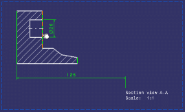
Select a line as shown below.

The Profile Definition dialog box appears, displaying the name of the 3D profile you are creating in the Name box. The geometry you selected is displayed in the Input Geometry list. The resulting geometry (that is all geometrical elements that eventually make up the 3D profile) is displayed in the Output Geometry list.
Tip: You can select an element from these lists if you want it to be highlighted in the 2D and 3D area. - Enter a name for your 3D profile, Shaft for example.
- Optionally choose a color for your 3D profile (the color is not applied to the geometry referenced by the profile).
-
Choose a mode from the associated drop-down list.
-
Point (Explicit Definition): you need to select all the points of interest. In that case, the Input Geometry and Output Geometry boxes show the same elements.
-
Wire (Automatic Propagation): after you select a geometrical element, the application detects and selects all connex elements. In that case, there might be more elements listed in the Output Geometry box than inInput Geometry
Important: In certain specific geometrical configurations, an ambiguity may arise, in which case some elements in the profile remain unselected. You can solve the ambiguity by selecting the remaining elements to include in the profile. -
Wire (Explicit Definition): you need to select the geometrical element of interest. In that case, the Input Geometry and the Output Geometry boxes show the same element.
-
Wire (Automatic Propagation, multiple profiles): after you select several geometrical elements, the application detects and selects all connex elements. In that case, each input geometry leads to the creation of several output geometries; in turn, each output geometry leads to the creation of a single profile, which ultimately leads to the creation of multiple profiles (so there might be more elements listed in the Output Geometry box than inInput Geometry).
Wire (Explicit Definition, multiple profiles): you need to select all the geometries of interest. In that case, the Input Geometry and the Output Geometry boxes show the same elements. Each output geometry leads to the creation of a single 3D profile.
Note: All 3D profiles created with Wire (Automatic Propagation, multiple profiles) and Wire (Explicit Definition, multiple profiles) will have the same color and support plane.Important: When selecting any Automatic Propagation mode, in the case of a view containing numerous geometrical elements, a message is displayed to inform you that the operation may be time-consuming. Click Yes in the dialog box to confirm that you want to launch the automatic propagation mode anyway. Clicking No selects the corresponding Explicit Definition mode (i.e. Automatic Propagation, single profile turns into Explicit definition, single profile and Automatic Propagation, multiple profiles turns into Explicit definition, multiple profiles). For this scenario, make sure the Wire (Automatic Propagation) option is selected from the list.
-
-
Optionally choose one or several checks to perform. This
is to verify that the profile is usable for solid or surface definition.
-
Check tangency
-
Check connexity
-
Check manifold
-
Check curvature
Note: These options are disabled if you selected Wire (Automatic Propagation, multiple profiles) or Wire (Explicit Definition, multiple profiles).Once checks are performed, warning messages may appear to help you decide whether you can keep your definition as such or if you need to modify it. Note that you can validate the profile definition even if there are some warnings. However, when updating the 3D, you may get an update error (depending on the kind of warning).
-
-
Click OK to validate and close the dialog box.
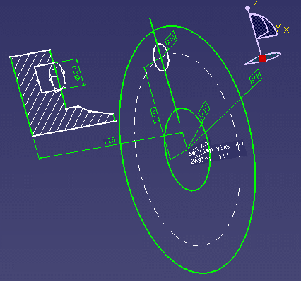
The 3D profile is created, on the same plane as the section view, and it
is listed in the tree, under the PartBody node.

Important: - Of all elements created from 2D geometry in 2D Layout for 3D Design, only 3D profiles and 3D planes belong to the current 3D shape body.
- Note that 3D profiles and 3D planes are created under the current 3D shape body
only when working in a hybrid design environment, that is when the
Enable hybrid design inside part bodies and bodies check
box is selected in
Me
 > Preferences > Common Preferences
> Object Properties > 3D Shape > 3D Shape Infrastructure expander, under Hybrid Design, (which is the
case by default). Otherwise, when this check box is not selected, 3D profiles and
3D planes are created in geometrical sets or ordered geometrical sets.


