Annotation Parameters | ||||||
|
| |||||
Annotation Texts
| Parameter | Description | Parent standard | Value | Description |
|---|---|---|---|---|
| Text > Leader Gap | Horizontal offset between the text and the leader extremity | ANSI and ASME only | (mm) |
|
| Text > Leader Vertical Space | Vertical offset between the bottom of the text and the horizontal part of the leader | ISO and JIS only | (mm) |
|
Surface Texture
| Parameter | Description | Parent standard | Value | Description |
|---|---|---|---|---|
| Surface Texture > Layout | Layout of the surface texture symbol | All standards | Authorized/Not authorized | Specifies whether a given field must be displayed (Authorized) or hidden (Not authorized) in the Surface Texture dialog box. |
| Surface Texture > Leader Gap | Horizontal offset between the surface texture and the leader extremity | ANSI and ASME All standards |
(mm) |
|
| Surface Texture > Leader Vertical Space | Vertical offset between the bottom of the roughness and the horizontal part of the leader | All standards | (mm) |
|
| Surface Texture > Extension Line > Thickness > Behavior | Behavior of the extension line thickness | All standards | Fixed / Variable with symbol | Specifies whether the thickness of the extension line must be fixed (using the value specified by the Line Thickness parameter below) or variable (using the graphic property of the thickness symbol itself). |
| Surface Texture > Extension Line > Thickness > Line Thickness | Extension line thickness index | All standards | Integer | Specifies the line thickness index (as defined in the LineThickness node of the current standard) that must be used to represent the extension line. This parameter is taken into account only if the Behavior parameter is specified to Fixed. |
| Surface Texture > Extension Line > Gap to surface | Extension line gap to surface | All standards | (mm) | Specifies the gap between the extension line and
the pointed object.
|
| Surface Texture > Extension Line > Length according to symbol | Extension line length defined according to symbol or not | All standards | Yes/No | Specifies whether the extension line length must be defined according
to the roughness symbol length. With value specified to Yes:
With value specified to No:
|
| Surface Texture > Extension Line > Overrun | Extension line overrun | All standards | (mm) | Specifies the overrun of the extension line. When the Length according to symbol parameter is specified to Yes: 
When Length according to the symbol parameter is specified to No: 
|
| Surface Texture > Leader anchor according to standard (for ANSI and ASME) | Leader anchor | for ANSI and ASME only | Yes/No | In the case of ANSI or ASME standard, specifies whether the roughness leader anchor parameter must be the normalized standard, that is, the Leader Vertical Space parameter (with value specified to Yes) or the Leader Gap parameter (with value specified to No). |
Blank Background
| Parameter | Value | Description |
|---|---|---|
| Blank Background > Around Value > Extend To Frame | Yes/No |
|
| Blank Background > Around Value > Margin | (mm) |
By default, the value is 1 mm. |
| Blank Background > Around Symbol > Activated | Yes/No |
|
| Blank Background > Around Symbol > Margin | (mm) |
By default, the value is 0.5 mm. |
| Blank Background > Around Symbol > Margin Around Sensitive Point | (mm) |
By default, the value is 0.2 mm. |
Welding
| Parameter | Value | Description | ||||||
|---|---|---|---|---|---|---|---|---|
| Welding Staggered Display | Usual/Alternative |
Usual - Adds the staggered (Z) symbol in the welding symbol. Alternative - Offsets the welding symbols on the opposite side of the reference line. |
||||||
| Welding Staggered Display Offset | (mm) |
Specifies the welding symbol offset. By default, the value is 5 mm. |
||||||
| Welding Display > System-A |
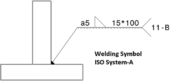
The symbolic representation of this system is based on a double reference line: a continuous line and a dashed line. |
|||||||
| Welding Display > System-B |
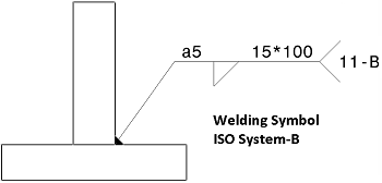
The symbolic representation of this system is based on a unique reference line. |
|||||||
| Overrun | By default, the value is 1.0. | The overrun is equal to the font size. | ||||||
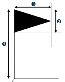
| Flag Display > Parameter 1 |
By default, the value is 1.5. |
|
||||||
| Flag Display > Parameter 2 |
By default, the value is 0.5. |
|||||||
| Flag Display > Parameter 3 |
By default, the value is 0.8. |


Tolerance
Expand Allow supplement Auxiliary Feature Indicators to customize the following standards:
| Parameter | Value | Description |
|---|---|---|
| Intersection Plane | Yes/No | Select Yes to add to the list of Auxiliary Feature Indicators in the Geometrical Tolerance dialog box. |
| Orientation Plane | Yes/ No | Select Yes to add to the list of Auxiliary Feature Indicators in the Geometrical Tolerance dialog box. |
| Collection Plane | Yes/No | Select Yes to add to the list of Auxiliary Feature Indicators in the Geometrical Tolerance dialog box. |
| Direction Feature | Yes/No | Select Yes to add to the list of Auxiliary Feature Indicators in the Geometrical Tolerance dialog box. |
The default values are Yes for ISO and JIS standards and No for ANSI-ASME standard.
Edge of Undefined Shape
| Parameter | Value | Description |
|---|---|---|
| Leader Vertical Space | mm |
By default, the value is 3mm. |
| Offset 1 | multiplying factor |
By default, the value is 0.2. |
| Offset 2 | multiplying factor |
By default, the value is 0.2. |
| Offset 3 | multiplying factor |
By default, the value is 0.3. |
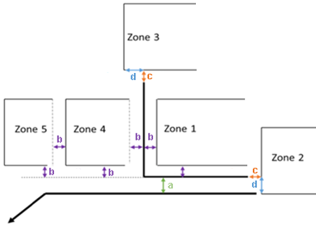
| Description | |
|---|---|
| a | Leader vertical space |
| b | Offset 1*Font size |
| c | Offset 2*Font size |
| d | Offset 3*Font size |