Adding 3D Constraints

Persistent 3D constraints are used to associate and restrict a variety of geometries. There are two main types of constraints: geometric and dimensional. A geometric constraint is a relationship that forces a limitation between one or more geometric elements. A dimensional constraint is a constraint whose value determines measurements of a geometric object.

You can add a 3D constraint between the lines, points, or vertices of linear wires. For example: 3D constraint creation is possible between two adjacent lines, or between a line and a non-adjacent curve. The available constraints on vertex and linear edge entities are the same as for the surface shapes. You can create a group of wire elements and the behavior of this group is the same as for a group of adjacent faces.

You can also add a 3D constraint between a face, edge, or vertex of a natural shape and a feature of an external app (for example, Part Design or Generative Shape Design).

  1. Select the faces, edges, and vertices you want to constrain. In this example, two faces.
  2. Select the type of constraint you want to apply. In this example, Distance is used to create a dimensional constraint.

    The context toolbar shows only those constraints that can be applied to the current selection.
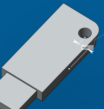
    By default, 3D dimensions (distance, angle, radius) are driving dimensions .

  3. To change the dimension type to driven, click Driven Dimension .
  4. To orient a constraint and ensure that the geometry moves in the desired direction, click the appropriate option in the context toolbar.

    Orienting a constraint determines which side moves. An arrow shows the side that changes.

    Notes:
    • If multiple constraints are added, constraints are solved as a system and the best possible solution determined. In this case, you may not get the expected result.
    • If one side is an external app feature, the constraint is always oriented from the external feature to the natural shape.

  5. Optional: Drag to move and correctly position the graphical representation of the constraint.
  6. To re-route constraints and change the anchor point, select the constraint and do one of the following:
    • Drag the handle to another geometric entity.
    • Click the handle, and then in the context toolbar, click Reroute and select another geometric entity.
    • For circular edges, cylinders and spheres, click the handle and then, in the context toolbar, select the precise option you want to use.

      The context toolbar shows only those options that apply to the current selection. Available options are the center point, the axis, the shortest distance and the longest distance.

  7. To edit a 3D driving dimension, do either of the following:
    • Click the value, enter a new value in the callout, then press Enter.
    • Pause over the graphical representation of the constraint and drag one of the arrows.

      Dragging an arrow lets you determine which side you want to move.