About 3D Constraints | ||||
|
| |||
Types
The following geometric relationships and 3D dimensions are available:
| Command Icon | Geometric Relationship | 3D Dimension | Definition |
|---|---|---|---|
| Fix element in position (single elements) | - | The Fix constraint locks a selected geometry to an absolute position. | |
| Coincidence | - | The Coincidence constraint aligns selected geometries on the same plane. | |
| Perpendicularity | - | The Perpendicularity constraint creates a 90-degree angle for two selected geometries. | |
| Parallelism | - | The Parallelism constraint positions selected geometries in a parallel position. | |
| Tangency | - | The Tangency constraint creates a tangency between two selected geometries. | |
| Symmetry | - | The Symmetry constraint creates a set of equal dimensions between two selected geometries. The picker is used to select the reference geometry. | |
| - | Distance | The Distance constraint lets you edit a distance value in the Selection Panel. | |
| - | Angle | The Angle constraint lets you edit an angle value in the Selection Panel. | |
| - | Radius dimension (cylinders) | The Radius constraint lets you edit a radius value between cylinders in the Selection Panel. |
There are two types of 3D dimensions:
- Driving dimension

- Driving dimensions are user-defined and constrain geometry to the value specified. They do not update to reflect changes to content such as element moves. This is the default 3D dimension type.
- Driven dimension

- Driven dimensions are measured dimensions. They update to reflect changes to content, but cannot be edited. Driven dimensions appear with brackets around the dimension value, for example, (30).
Available Constraints by Entity
This table identifies the 3D constraints that can be created between the combinations of geometric entities listed below.
| Vertex | Linear Edge | Cylindrical Edge | Planar Face | Cylindrical Face | |
| Vertex | - | - | - | - | |
| Linear Edge |
| - | - | - | |
| Cylindrical Edge |
|
| - | - | |
| Planar Face |
|
|
| - | |
| Cylindrical Face |
|
|
|
|
For cylinders and spheres, the table identifies the 3D constraints that can be created between the combinations of characteristic elements listed below.
| Center | Axis | Face | |
| Center | - | - | |
| Axis |
| - | |
| Face |
Angle Constraints
Angle sector options in the Selection Panel give you control over how the angle is measured. Four angle sectors are available.
Angle sector 1: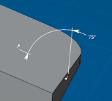 | Angle sector 2: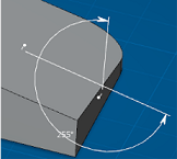 |
Angle sector 3: 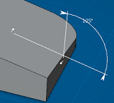 | Angle sector 4: 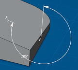 |
Orientation
Orientation options in the Selection Panel let you specify how elements move with respect to each other.
- Orient the constraint


- Orienting a constraint determines which side moves. An arrow shows the side that changes. Notes:
- If multiple constraints are added, constraints are solved as a system and the best possible solution determined. In this case, you may not get the expected result.
- If one side is an external app feature, the constraint is always oriented from the external feature to the natural shape.
- No orientation

- The system controls how elements move with respect to each other.
Multiple Constraints
Making a multiple selection of faces, edges and vertices lets you create all corresponding 3D constraints in one go.
The last element selected is the reference. Multiple constraints are created with respect to this reference. For example, dimensions are applied with respect to this face (in blue below):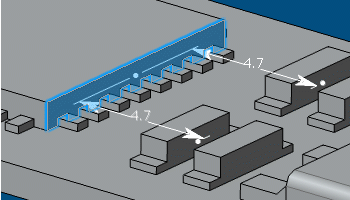
Constraint Status Conventions
3D constraints are displayed in different colors to facilitate identification and, if necessary, to repair.
- Over-constrained
- One or more constraints are over defining the shape. Dimensions or relations are in conflict or are redundant.
Appear in the color set in the Overconstrained constraint style option in .
External App Features
When adding a 3D constraint, the external feature is copied locally as an External Reference (visible in the tree) and the 3D constraint references this external reference. The 3D constraint is oriented from the external reference to the natural shape and any changes affect the natural shape only.
Adding and rerouting a 3D constraint between an external app feature and a natural shape is unavailable if:
- A mirror plane exists.
- A constraint already exists between the natural shape you want to constrain and another natural shape.
- The external feature is based on the natural shape you want to constrain.
Similarly, if a 3D constraint with an external feature exists:
- The Mirror command is unavailable.
- You cannot add or reroute constraints between the constrained natural shape and another natural shape.
- You cannot base the external feature on a constrained natural shape.