About the User Experience | ||
| ||
Overview
At its core, the user interface concept offers a highly intuitive environment. By making every command accessible through the action bar, users have a highly predictable environment where the most common commands automatically emerge in the Selection Bar when an element is created or selected. The main enhancements include:
- Automatic emergence of all relevant commands in the Selection Bar when selecting an element;
- Permanent placement of the Selection Panel for more advanced commands;
- Ease of modifications thanks to immersive 3D handles and editors;
- Simplified validation by clicking in empty space, selecting a new element, or launching a new command.

User Experience and Interactions
| Common Features | Description | Icon |
|---|---|---|
| Action Bar | The action bar places every Natural Shape command in a readily accessible location for intuitive design and modification. |
|
Selection Panel 
|
The Selection Panel lets you use more advanced commands. | - |
Selection Bar 
|
The Selection Bar automatically emerges when a geometry is selected. In addition to displaying information about the current selection, it provides access to a set of relevant commands by propagating the selection tool. |
|
| Selection propagation |
When a selection is extended out of a command, the content of the action bar, Selection Bar, and available handles are updated. When a selection is extended during a command, the current command is validated and selection propagation is applied to previously highlighted elements. Available commands are ready to be launched. |
|


Interactions
| Interactions | Explanation |
|---|---|
Manipulators 
|
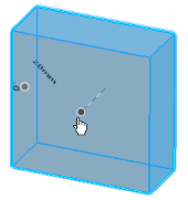
Manipulators offer a way for users to directly interact with their geometry by automatically emerging when an element is selected. They suggest the most appropriate commands based on that selection. If the element's type and characteristics permit, you can perform an operation directly within the handle function, otherwise, the Selection Bar appears so that you can select the most suitable command. When multiple elements are selected, the options in the Selection Bar offer only applicable commands to the specific elements. The default handles are clickable when a command is launched.
Upon clicking, the associated editor in the Selection Panel
automatically displays values specific to the selection,
enabling you to modify any relative values from the keyboard.
|
Picker 
|
Multiple pickers capture a scene's information. They are the axis, length, angle, reference, and point pickers:
|
| Boolean Operations |
Boolean operations occur in the event of clashing and offer four dedicated options for each command in the Selection Panel:
Note:
Use these operations to generate a single body resulting from
the intersection.
|
| Interrupt | An interrupt feature occurs automatically to inhibit sequential updates from taking place. This is particularly useful for complex parts that could be subject to insufficient performance because of their complexity. |
| Validation | There are multiple ways to validate in-process operations. You can click geometry, a command icon, or anywhere in the empty space to start a new command. When selecting geometry, the Selection Bar and most suitable command handles appear. |


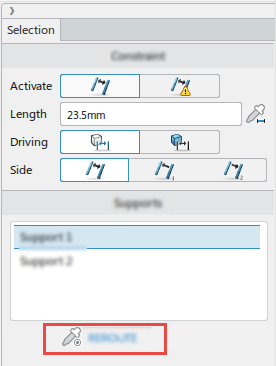
Constraints and Supports
You can edit and create constraint supports directly in the
Supports section of the Selection Panel. The panel to edit
constraints appears when you select the 3D constraint or its node in the tree. 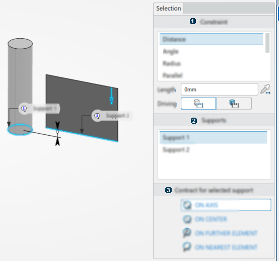
| Selection Panel | Description |
|---|---|
|
|
Constraint |
|
|
Supports |
|
|
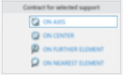
Contract for selected support |
The panel to edit constraints appears when you select the 3D constraint or its node
in the tree. 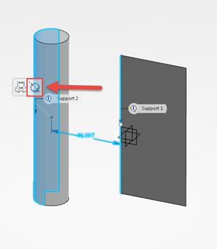
A REROUTE command is used during the editing of a 3D constraint.
It is possible to select the constraint location based on the selected support. For example:
| Selection Panel | Description |
|---|---|

|
ON AXIS |

|
ON CENTER |

|
ON FARTHEST ELEMENT |

|
ON NEAREST ELEMENT |
 is used to
select a new geometry.
is used to
select a new geometry. Move Commands
Natural Shape uses a specific Robot and handles as move commands that enhance the User Experience. These graphical
handles help you to translate and rotate geometries along three different directions
while rulers provide added precision. 
| Handles | Description |
|---|---|
|
|
Robot axis handle focused on the V direction and a moved Vertex in the middle. |
|
|
Length ruler focused on the V direction. |
|
|
Reference handle. |
| Direction/Rotation | Planar Translation | Color |
|---|---|---|
| W | UV |  |
| V | UW |  |
| U | VW |  |
The Robot handle is composed of three direction handles along its local U, V, and W
directions. In addition, there are three rotation handles around the U, V, and W
directions as well as three planar translation handles along the UV, VW, and UW
planes. 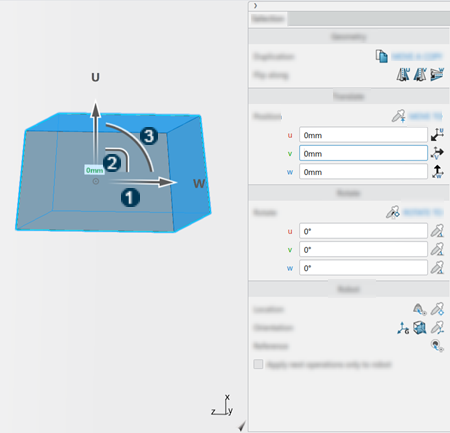
| Handle | Description |
|---|---|
|
|
Robot axis handle focused on the W direction. |
|
|
Planar handles are inside of the rotation handles. |
|
|
Arc circles represent rotation handles. |
Direct access to the various handles is possible by clicking the
Move command in
the selection bar after selecting a volume, surface, or face.
command in
the selection bar after selecting a volume, surface, or face.
Move Command Selection Panel and Functionality
The Selection Panel of the Move command
provides a multitude of functions. The following tables describe each section.
| Command | Description | |
|---|---|---|
| Duplication |  MOVE A
COPY MOVE A
COPY |
Duplicates a moved object. |
| Flip along U |  |
Flips the moved object around U. |
| Flip along V |  |
Flips the moved object around V. |
| Flip along W |  |
Flips the moved object around W. |
| Position | Description | |
|---|---|---|
| MOVE TO |  |
Moves to picked position. |
| u |  |
Aligns U to picked position. |
| v |  |
Aligns V to picked position. |
| w |  |
Aligns W to picked position. |
| Rotate | Description | |
|---|---|---|
| ROTATE TO |  |
Rotate to picked position. |
| u |  |
Lets you pick a rotation angle value in 3D. |
| v | |
Lets you pick a rotation angle value in 3D. |
| w | |
Lets you pick a rotation angle value in 3D. |
| Command | Description | |
|---|---|---|
| Location |
|
|
| Orientation |
|
|
| Reference |  |
Lets you use the current position as a length reference. |
| Apply next operations only to robot. |  |
Reorients the robot to start a manipulation from there. |


