Experiencing 3D Motion Study of Mechanisms | ||
| ||
-
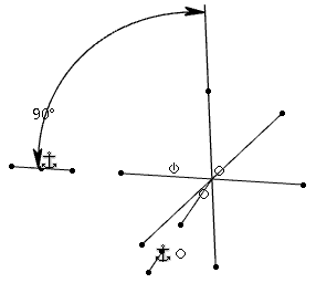
Create a geometry with wires in Natural Shape.
In this example, there are two edges and a propeller.
-
To create a rigid set and represent a body of the mechanism, create a group for each geometry element.
- Select an edge and, on the context toolbar, click Group
 . Do the same for the other edge.
 - Select the propeller and click Group .
Three groups have been created.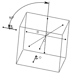
The origin and the absolute axis of the geometry are treated as immovable. One edge is used to create the angular constraint, the other one is the axis around which the propeller will rotate.
Internal constraints of each body are irrelevant to the kinematic system. Only external constraints are considered for the kinematic relation between the bodies of mechanism.
- Select an edge and, on the context toolbar, click Group
- Anchor or ground the bodies to make them immovable using Fix
 .
. -
From the Compass, click Play
 .
.
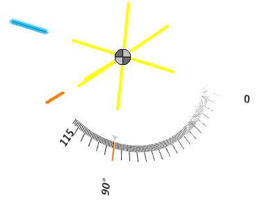
- You are now in the motion study environment. Each body is colored uniquely.
- The detected relation between the two bodies appears with the
 icon for a rotation-based relation and
  for a translation-based relation.
 - The Play section is added to the action bar.

- Select an individual body and drag along the ruler to change its position.
- To create an angular motor in the mechanism, click , and
 on the context toolbar.
If a linear link is recognized for a joint, click
, and  on the context toolbar to create a linear motor in the mechanism.
 -
From the Play section of the action bar, click Play Forward
 .
The mechanism can be now experienced. The propeller turns.
.
The mechanism can be now experienced. The propeller turns.The Play section includes the following commands:
Command Description 
- Step Backward
- Goes back to the beginning of the scenario.
- Play Forward
- Plays the scenario.

- Step Forward
- Moves to the end of the scenario.

- Decrease Speed
- Decreases the scenario speed.

- Pause
- Pauses the scenario.

- Increase Speed
- Increases the scenario speed.
- From the action bar, click Exit or from the Compass, click Play to exit the motion study environment.
If you re-enter the motion study environment in the same session, the values you assigned are restored.
Notes:- Since the values assigned to the motor are based on the constraints you apply to the geometry, the motor is reset if the concerned constraints are removed.
- Delete the motor and assign new values to disregard the previous values assigned to the motor.