You can define a rule to mesh around oblong holes by specifying the minimum
and maximum diameter and the minimum and maximum width.
Oblong holes are holes
that are not perfectly circular, such as an oval. Oblong holes have a length component and a
width component.
-
Select the Feature section, and select 2D
Holes
 as the feature
type.
as the feature
type.
-
Select Oblong as the Hole type, and
select Mesh around hole.
The Mesh around hole dialog box appears.
-
Define the holes you want considered by the rule.
- Select Minimum diameter, and enter a value to ignore the
rule for holes with a diameter less than this imposed minimum.
- Select Maximum diameter, and enter a value to ignore the
rule for holes with a diameter greater than this imposed maximum.
- Select Minimum width, and enter a value to ignore the
rule for holes with a width less than this imposed minimum.
- Select Maximum width, and enter a value to ignore the
rule for holes with a width greater than this imposed maximum.
If you clear a field, no threshold value is imposed for the corresponding
parameter.
-
Select a Mesh with method to specify how the number of mesh
edges around holes is to be treated.
| Option | Description |
|---|
| Min. number of edges |
Meshes holes using at least the specified number of element edges; more edges
might be added to match the surrounding mesh size. |
| Exact number of edges |
Meshes holes with exactly the specified number of element edges. |
-
Enter a value for the exact or minimum Number of edges to be
used around each hole (depending on which method you specified in the previous
step).
-
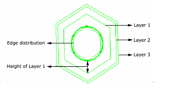
In the Layer list, select the number of layers you want to use
to mesh around the holes affected by the rule.

-
Specify the height of each layer.
If you clear the field for a layer height, the rule mesh algorithm computes a value
automatically.
-
Click OK in the Mesh around Hole dialog
box.