Connection Manager

The Connection Manager displays a list of the simulation connections in your model in a simple list or in a tree view that shows the connections under their respective engineering connections. You can review, update, or deactivate connections using the manager.

This page discusses:

Overview

The Connection Manager provides a convenient way to work with all of the connections in your model. You can review the properties and status of the connections, control visibility, and perform other actions.

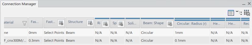
By default, the Connection Manager displays a flat list of the simulation connections in your model, as shown below.

You can use the icons at the upper right of the Connection Manager to switch between the default view and the tree view. The tree view is based on the product structure, with the simulations grouped under their respective engineering connections. This view allows you to see all the engineering connections and assembly constraints on the model in addition to the simulation connections. The tree view is shown below.


By default, the following columns are displayed in the Connection Manager:

Column name Description
Include state Check boxes for including or excluding connections from the current FEM.
View state Toggle for hiding () or showing () the connection.
Engineering Connection Engineering Connection used by the connection.
Name Connection name.
Connection Mesh Mesh object associated with the connection.
Type Connection type.
FEM Rep FEM representation in which the connection is included.
Status Status of the connection:
  • OK (green): Connection is included, valid, and mesh is up-to-date
  • Not realized (orange): Connection is valid and included but mesh is not created or has been removed
  • To be updated (orange): Engineering connection is created or modified (connection is valid and included)
  • Needs upgrade (orange): Upgrade is required for connection (connection is valid and included)
  • Supports not loaded (orange): Connection is included, but supports are based on entities that are not loaded
  • Invalid (red): Connection is invalid
    Tip: Hover over this status to see diagnosis.
  • Supports deleted (red)
  • Deactivated (black)
  • Excluded (black): Connection is excluded from the current FEM. When a connection is excluded, the FEM Rep and Connection Mesh columns are empty.
Template Name of template used to define the connection properties.
Number of components Number of connected parts.
Component 1 Name of the first connected part.
Component 2 Name of the second connected part.
Description Key attributes of connection definition, such as the construct or coupling type.
Material Material used in connection elements (where applicable).

You can display the following additional columns by right-clicking on any column header and selecting Hide/Show columns:

  • Component 3
  • Remaining components

Applying Filters and Sorting

You can right-click any column header to sort the table alphabetically based on the selected column.

You can filter the list using the filter icons in each column. You can filter by name or feature type, depending on the type of data in the column. To access the filter for a column, click its filter icon . Define your filter, and click the check mark to apply it to the table. When a filter is active on a column, it is displayed in a darker color . To temporarily disable a filter without clearing its settings, click the filter icon and then click Deactivate .

Expanding Columns in the Filtered View

When you set the filter to show only one type of connection, you can display additional columns showing information specific to that connection type. For example, if the filter is set to show only point fasteners, you can see these additional columns:

  • Fastener diameter
  • Fastener placement method
  • Structure
  • Coupling type
  • Weighting method
  • Coupled faces
  • Maximum projection distance
  • Maximum angle
  • Maximum angle between adjacent faces
  • Adjust tolerance
  • Height
Click to show the additional columns. You can use Hide/Show columns in the context menu to control the display of these columns individually.

Some of the additional columns can be further expanded to show more parameters. For example, for point fasteners you can click to show more columns. You can then expand the structure column to view the beam shape column, which in turn can be expanded to show the dimensions used to define the shape.

Modifying Connection Status from the Manager

The Connection Manager enables you to include and exclude connections in the active finite element model (FEM) without deleting them. If the connection is included in the current FEM, you can click the check box to the left of the connection to include or exclude the connection. If the connection is included in a child FEM representation (defined in an assembly of meshes), the check box is read-only. To activate and deactivate this connection, you must change the active FEM representation by right-clicking on the feature in the Connection Manager and selecting Switch to including FEM representation.

Right-click on the connection row to show the context menu, which has the following options:

Option Description
Edit Opens the editor for the connection
Tip: You can edit common properties of multiple tie, point, and line fasteners at the same time by using Edit in the context menu after selecting the fasteners. Press Ctrl to select multiple fasteners. The editor indicates how many fasteners are included in the edit.
Hide/Show Toggles the fastener glyph visibility.
Review Opens the connection review toolbar. The connection review toolbar allows you to hide, show, or show only that connection.
Locate Zooms the view on the selected connection.
Center tree on property Centers the Model Tree on the connection feature.
Center tree on mesh Centers the Model Tree on the connection mesh.
Upgrade Upgrades the connection. This option appears only when the connection was defined in an earlier version.
Exclude/Include Excludes or includes the connection. When a connection is excluded, its mesh part is deleted and is not regenerated when the FEM is updated.
Delete Deletes the connection from all FEMs.
Update Mesh Creates the mesh nodes and elements.
Remove Mesh Removes the mesh without deleting the connection definition.
Deactivate/Activate Mesh Deactivates or activates the connection mesh.
Load Supports Loads the geometry or mesh entities used as supports for the connection. This option appears only if these entities are not yet loaded.
Reload parameters from template Updates the connection parameters from the template. This option appears only if you used a template to define the connection and the template has since been modified.
Create weld curve Projects the weld curve onto the connected parts. This option appears for line fasteners under the following conditions:
  • The mesh is defined for the connected supports.
  • Mesh local specifications have not yet been created.
  • The weld curve parameters have been defined as part of the line fastener definition.

Moving a Connection Mesh to a Different FEM Rep

You can move a connection mesh from a child FEM to the parent FEM as follows:

  1. In the child FEM, open the Connection Manager and deactivate the connection.
  2. Switch to the parent FEM.
  3. Use the Connection Manager to activate the connection in the new context.