Composite Property Mapping on Multiple Layers | |
| |
The process of mapping composite data on a multi-layered mesh starts with core sampling, in which the elements of each layer of the mesh are retrieved and considered for mapping. Core sampling depends on the node ordering and thickness direction of the elements in your mesh; for more information, refer to the related topics in the Abaqus user assistance.
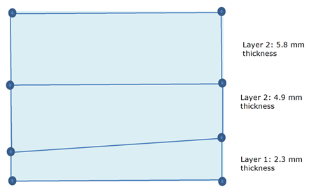
Once core mapping is complete, composite continuum shell properties are mapped using an approach that is illustrated in the following figure.


In this example the algorithm performs ply distribution for each layer as follows:
- Layer 1: Element mapped with Ply.1 (1 mm), Ply.2 (1 mm), and Ply.3 (0.3 mm).
- Layer 2: Element mapped with Ply.3 (0.7 mm), Ply.4 (1 mm), Ply.5 (1 mm), and Ply.6 (2.2 mm).
- Layer 3: Element mapped with Ply.6 (0.8 mm), Ply.7 (1 mm), Ply.8 (1 mm), Ply.9 (1 mm), Ply.10 (1 mm), and Ply.11 (1 mm).
Ply.3 is shared between Layer 1 and Layer 2, with its thickness shared proportionally between the two. Ply.6 is shared in a similar way between Layer 2 and Layer 3.