Defining Acoustic Domains | ||||
|
| |||
-
From the Abstractions section of the action bar, click Acoustic Domain
 .
.
-
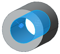
Define the three-dimensional region in which the fluid flows.
- Expand the Regions container, and click Add Region.
-
Select the geometry support.
Select one or more surfaces as the geometry support. Select the surface that encloses the cavity that is filled by the fluid—for example, the inner wall of a pipe. You can select a face group to define this support.
A glyph is displayed in the model to show the location of the
fluid.
is displayed in the model to show the location of the
fluid.
-
If necessary, click
Flip direction to change the side of the
surface on which the fluid flows. For example, the glyph in the figure below
shows that the fluid is located inside the pipe.
-
Select the structure's inlets and outlets through which the fluid flows.
Specify the location of all inlets and outlets, but you do not differentiate
between them in this procedure.
- Expand the Inlets/Outlets container, and click Add Inlet/Outlet.
-
Select the geometry support.
You must select a closed loop as the geometry support. In the figure below, the circular inner edge of the pipe opening is selected. You can select an edge group for this support.
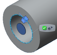
A circular disc glyph shows the location of the inlet or outlet opening. - Repeat steps a and b to select as many inlets and outlets as necessary in the model. For example, a car's exhaust manifold might have four inlets and one outlet.
After you create the acoustic domain, it becomes part of the simulation model and can be seen in the tree under the Abstractions node of the FEM representation.