-
From
the Projection options, select one of the
following:
| Option | Description |
|---|
| T Joint |
Defines a joint where the smallest angle between the supports is
greater than 45 degrees. |
| Lap Joint |
Defines a joint where the smallest angle between the supports is
less than 45 degrees. |
-
Select the Penetration type to extend the mesh at the
intersection to fill the gap between the two supports.
| Option | Description |
|---|
| None |
Does not create extra elements at the gap. |
| Partial |
Creates elements to fill the gap between the supports, with duplicate nodes at the
intersection. |
| Full |
Creates elements to fill the gap between the supports, with shared
nodes at the intersection. |
-
Select the appropriate Fillet type
(None, Single sided, or
Double sided (T joint only), as shown below).
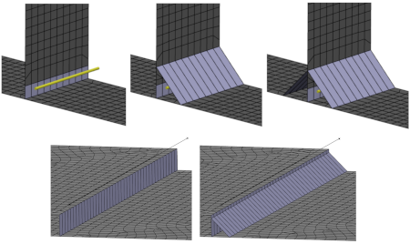
-
If you included fillets, enter Offset 1 and
Offset 2, which are offsets from the intersection of
the parts. In the above image, Offset 1 is in the
vertical direction, and Offset 2 is in the horizontal
direction.
-
If you included fillets, enter the Fillet Thickness,
which is the thickness of the shell section that represents the weld
fillets.
-
Specify the Maximum projection distance, which defines
the maximum gap (distance) between the placement geometry and the body you are
connecting.
The fastener is not created if the placement geometry and the body are farther
apart than this distance.
-
Specify the Maximum angle, which is the limit for the
angle of inclination between the two surfaces being fastened.
The app creates the fastener mesh even if the angle is exceeded. However, it issues a mesh
warning.
- Optional:
Do the following to define the Mesh around the fastener:
-
From the Realization options section of the
dialog box, click
 to edit
the settings for the mesh around the projected weld curve. to edit
the settings for the mesh around the projected weld curve.
-
Specify the Number of Layersto surround the weld
projection. You can specify between 0 and 4 layers.
-
Specify the Height of layer 1 (layer 2, etc.),
which defines the size of each of the layers surrounding the weld
projection.
In
the example below, the yellow highlights show the regions created by the mesh
around the fastener settings.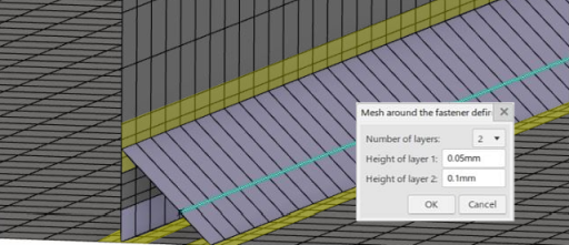
-
Select the Spacing defined by option to indicate the
method used to determine how many element edges are created along the projected
weld curves:
| Option | Description |
|---|
| Mesh Size |
Uses the part mesh to determine the element size. |
| Number of Edges |
Specifies the element size to accommodate the user-specified number
of edges. |
| Local Size |
Specifies the element size to a user-specified value input. |
-
Specify the Number of layers to control the number of
elements through the gap height or through the fillet face.
-
Set the Layer distribution to one of the
following:
| Option | Description |
|---|
| Uniform |
Layers are the same height. |
| Arithmetic |
Layers vary by a constant value. |
| Geometric |
Layers vary by a constant ratio. |
-
For multiple layers with nonuniform distribution, specify the Layer
size ratio that controls the ratio of the largest to smallest
layer size.
- Optional:
Select Symmetric layers to make the layer distribution
symmetrical.
|