- From the Mesh section of the action bar, click Tetrahedron
Filler Mesh
 . .The Tetrahedron Filler dialog box
appears. - Optional: Enter a Name for the tetrahedron filler mesh.
- Select the 2D mesh from which you want to generate the 3D mesh.
You can select one or several 2D
meshes (surface rules meshes,
Octree triangle meshes, coating 2D meshes,
and all 2D meshes created using the actions in the Operate section of the action bar). - Choose the type of 3D elements that you want to generate.
- Linear tetrahedron elements can be used to fill a solid with only straight edges.
- Parabolic tetrahedron elements can be used to fill a solid with curved edges.
The
element order of 3D generated elements is independent of the element order of the 2D source mesh. For example, you can generate parabolic tetrahedron elements from linear surface elements. - In the Size progression box, enter a factor to allow the mesh element size to increase inside the solid.
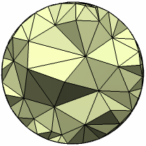
The size progression factor must be greater than or equal to 1. If you specify a size progression factor equal to 1, the size of the internal edges used to build tetrahedron elements is equal to the edge size of the 2D source elements. Example of a size progression equal to 2:
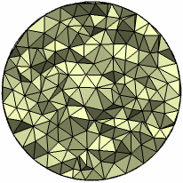
Example of a size progression equal to 1:
- Optional: Toggle on Multiple elements across narrow regions to prevent the inclusion of single elements that span the thickness of narrow model regions.
Using multiple elements in narrow regions can resolve convergence issues and significantly improve simulation results. You should consider the following conditions when activating this option: - The number of elements throughout the model will also increase, leading to an increase in meshing and simulation time.
- The narrow region elements might exhibit low quality due to the poor aspect ratios required to
conform to the geometry.
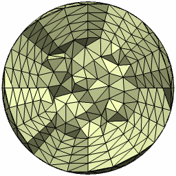
- Optional: Click Local Mesh Layers
 to add boundary layers to the mesh. to add boundary layers to the mesh.See Add Boundary Layers for detailed instructions. Example of a mesh specification with four layers and a uniform distribution:
- Click one of the following:
If you click OK or Apply, the 3D mesh specification is created and appears in the tree.
|