-
From the
Compass,
click
Simulation
Apps
and select the
Structural Model Creation
app.
Each time you enter a model creation app, a new finite element model representation is created.
The Create Finite Element Model dialog box appears.
-
Choose which geometries will be initialized as supports of the mesh:
| Option | Description |
|---|
| Main body in each shape |
Initializes the main body only (that is, the PartBody). If the
PartBody is empty, the app initializes another solid body. If all solid bodies are empty, the
app initializes any ordered geometric set until there is a single 3D
result. |
| All geometries in all shapes |
Initializes all geometries of the part or assembly. |
| Select geometries |
Enables you to select which geometries of the part or assembly to
initialize for meshing. |
If you choose Select geometries, you can view a list of
imported geometries eligible for initialization by clicking Show
advanced tree selection to open the Body
selection dialog box. You can filter and select your geometries
from this dialog box.
Note:
In the case of ordered geometric sets, the app initializes all 2D and 3D geometries as supports. For more information,
see Ordered Geometric Sets in the Structural Model Creation Guide.
-
Choose the initialization method for the finite element model:
| Option | Description |
|---|
| None |
Creates a finite element model representation without creating a
mesh. Instead, you define the mesh parameters during the
creation process. This approach ensures that the created mesh is
suitable for your simulation. |
| Automatic |
Creates an initial mesh automatically according to the default mesh settings. For 2D
geometries, the app creates a surface quad mesh. For 3D geometries, the app creates a tetrahedron mesh. |
| Manual |
Creates an initial mesh based on your specifications for mesh type,
element order, size, and sag ratio. |
| Rule-based |
Creates an initial mesh based on a set of parameters in a meshing
rules document that you select. For more
information about meshing rules, see Creating and Modifying Meshing Rules. |
| Procedure-based |
Creates an initial mesh based on a set of initialization instructions in a Visual
Basic script. When you choose procedure-based initialization, you must
also define the inputs for the initialization script using a meshing
rules document. For more information about procedures, see About
User Procedures in the Model Assembly Design Guide. The status icon next to the Define
inputs button changes from red to green once you define
all the required inputs for the procedure. |
-
If you selected the Manual initialization method, you
must specify the following parameters:
-
Select the Mesh type.
-
Select the Element order, linear or
quadratic.
-
Specify the element Size.
The mesher might vary the element size to improve quality, conformance to geometry, or
other parameters.
-
If you selected Sweep 3D Mesh for solid
geometries, specify the Number of layers.
-
If you selected any other mesh type, specify the Sag
ratio.
The sag ratio controls the degree of conformance between the
mesh and curved geometry. It is the ratio of the maximum distance
between an element edge and the geometry to the length of the element
edge.
-
If your model includes surface geometries without a defined thickness,
specify the Thickness of the shell section.
-
Select Create knowledge parameters to create
Knowledgeware parameters.
- Optional:
To choose new mesh quality criteria, select the Select specific
quality criteria option and open a saved quality criteria file.
By default, the criteria specified in the options () are used.
-
Click OK.
You should always use the Mesh Creation
app to review the mesh. You can then edit the mesh or delete it and create a
new one that is suitable for your simulation.
The FEM representation is created and displayed in the tree.
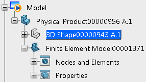
Finite Element Model00001371 contains two sets:
Nodes and Elements and Properties.
You can then create meshes (under the Nodes and Elements set)
while staying in your current modeling or scenario app;
for more information about creating meshes, see Meshing Geometries. To create meshes, you
must enter the Mesh Creation
app
to access the finite element representation tools.
To enter the Mesh Creation
app,
double-click the finite element model representation or an element belonging to the
finite element model representation:
 > Preferences) are used.